
- All
- Product Name
- Product Keyword
- Product Model
- Product Summary
- Product Description
- Multi Field Search


Views: 0 Author: Site Editor Publish Time: 2026-10-18 Origin: Site


Struggling to fine-tune motor velocity while maximizing torque? Tight industrial spaces and demanding operational loads make this engineering challenge even harder. Picture a standard AC motor spinning at 1500 RPM. Hook this directly to a packaging conveyor, and the belt moves uncontrollably fast. It will completely lack the pushing force needed to move heavy pallets.
A reliable Speed Reduction Gearbox serves as the ultimate mechanical bridge. It steps down frantic motor rotations to usable, muscle-bound power. Among the various power transmission solutions available today, the right-angle screw mechanism stands out for its rugged reliability and spatial efficiency.
In this comprehensive guide, we will demystify the core concepts behind these mechanisms. We will explain how gear configurations directly influence your system performance and provide actionable insights to help you select the perfect drive for your specific application.
To properly integrate a power transmission system into any industrial machinery, engineers must first understand the fundamental mechanics of speed reduction. The reduction ratio acts as the defining metric dictating how a transmission unit will alter the performance of an attached electric motor.
In mechanical engineering, this value represents the direct proportional relationship between the rotational speed of the input shaft and the final rotational speed of the output shaft. It serves as a true measure of mechanical advantage. When a motor operates at a high rotational speed, it is often too fast for standard industrial applications like heavy-duty mixers or assembly lines. A reducer steps down that frantic speed to a usable, controlled level.
For instance, if an application requires only 50 RPM to smoothly operate a bottling line, a specific configuration is necessary to bridge the gap between the motor and the load. This mathematical relationship not only dictates the drop in velocity but also governs the proportional increase in torque. A relatively small motor can therefore move massive loads without stalling out on the factory floor.
To truly grasp how these impressive numbers are achieved, you must peek inside the housing of a Worm Reducer. The system consists of two primary interlocking components. First, there is the input screw. Manufactured from hardened steel, it withstands high rotational friction. Second, there is the driven gear meshing with the screw. Manufacturers generally cast this wheel from softer materials like phosphor bronze. This deliberate material pairing ensures that sliding friction wears down the easily replaceable wheel rather than the critical steel input shaft.
The unique geometry of this pairing allows for massive speed reduction in a single stage. A single 360-degree rotation of a single-start thread will advance the matching wheel by exactly one tooth. Because of this screw-to-gear interaction, these drives achieve significant reductions in a much smaller footprint than traditional parallel-shaft gear sets.
Determining the correct parameters for your machinery relies on standard mathematical formulas. Relying on empirical data and strict calculations ensures that the selected industrial drive will not fail under heavy industrial loads.
Calculating the ratio is a straightforward process once you know the internal specifications of the gears. Unlike standard spur gears where you divide the number of teeth on the driven gear by the teeth on the driving gear, right-angle screw gears rely on the number of threads on the input shaft.
The standard engineering formula is simple: Reduction Ratio equals the Number of Teeth on the Wheel divided by the Number of Starts on the Input Shaft.
To illustrate this, consider the following empirical examples:
| Worm Shaft Starts Threads | Worm Wheel Teeth | Calculated Ratio |
|---|---|---|
| 1 Single-Start | 60 | 60:1 |
| 2 Double-Start | 60 | 30:1 |
| 4 Four-Start | 60 | 15:1 |
As demonstrated in the table, a single-start thread driving a 60-tooth wheel yields a 60:1 ratio. If you replace the input shaft with a double-start thread, the ratio halves to 30:1. Consequently, the wheel will turn twice as fast but deliver significantly less twisting force.
Once the ratio is locked in, determining the final Output Speed becomes your next critical step. This parameter dictates exactly how fast your conveyor belt will move or how quickly a winch will lift a payload.
The formula for this calculation requires dividing the Motor Input Speed in RPM by the Reduction Ratio.
Assume you are utilizing a standard 4-pole AC motor running at an input speed of 1400 RPM. You have selected a transmission unit with a 50:1 ratio. By dividing 1400 by 50, you get 28 RPM. The final rotational velocity of the driven shaft will be a steady 28 revolutions per minute. This predictable calculation allows engineers to precisely synchronize multiple moving parts within complex automated systems.
With various types of power transmission units available on the market, understanding the specific situational advantages of a screw-gear drive is vital for making an informed purchasing decision.
One of the most prominent reasons engineers specify this design is spatial efficiency. In real-world industrial environments, factory floor space and machinery housing dimensions are strictly limited. A single-stage right-angle unit can comfortably achieve reduction values ranging from 5:1 all the way up to 100:1.
In contrast, achieving a 100:1 ratio using standard helical gears requires engineers to design a multi-stage gearbox containing three or more separate gear sets. This results in a bulky, elongated housing. The right-angle drive accomplishes this massive reduction in a single stage. It utilizes a 90-degree shaft configuration that tucks neatly into tight corners and compact machinery frames.
Safety and load stability are paramount in applications such as hoists, elevators, and inclined conveyors. These specific gear pairings offer a unique mechanical property known as irreversibility. Because of the high sliding friction and the specific lead angle of the threads, it is often physically impossible for the load on the wheel to back-drive the motor.
When power is unexpectedly cut, the gear set holds the load firmly in place. Generally, a ratio of 50:1 or higher provides static self-locking. While external braking systems remain highly recommended for strict safety compliance, this inherent holding nature provides a critical secondary layer of operational security.
When evaluating power transmission solutions, buyers frequently weigh sliding-friction drives against helical gearboxes. Both serve the primary function of speed reduction, but they operate on entirely different kinematic principles.
The primary drawback of a high-ratio screw drive is mechanical efficiency. These gears transmit power through sliding friction. The steel screw actively rubs against the bronze wheel teeth, generating significant heat. At lower ratios like 10:1, efficiency remains around 85 to 90 percent. However, at extreme ratios like 80:1 or 100:1, efficiency can plummet to 50 percent or lower. This means half the motor power dissipates as thermal energy.
Furthermore, helical gearboxes utilize rolling friction. The teeth mesh and roll against one another, maintaining high efficiency ratings often above 95 percent regardless of the reduction value. Therefore, helical units generate far less heat and consume less electrical power over continuous operating cycles.
Despite the efficiency loss, sliding-friction gears dominate many sectors due to other compelling factors. They are highly cost-effective because they contain fewer internal moving parts. Their sliding action makes them exceptionally quiet. This serves as a major benefit in noise-sensitive environments like theaters or medical facilities. For intermittent operations where high torque, quiet operation, and low initial cost are prioritized, the right-angle drive is superior. Conversely, for continuous round-the-clock operations where energy consumption is the primary concern, a helical unit offers a better long-term return on investment.
Looking at current industrial trends, the global market for power transmission components is experiencing a distinct shift toward modularity and energy optimization. Recent engineering analyses highlight that while high-efficiency helical drives are gaining traction for continuous heavy-duty operations due to rising global energy costs, the demand for right-angle sliding-friction drives remains exceptionally strong in automation, material handling, and robotics.
Specifically, facility engineers are increasingly seeking hybrid solutions. Combining highly efficient AC motors with advanced, synthetic-lubricated right-angle drives strikes a perfect balance between spatial constraints, initial capital expenditure, and long-term operational costs. This industry-wide trend underscores the importance of precise ratio selection to minimize mechanical losses while maintaining indispensable self-locking safety features. Modern manufacturing simply demands compact, reliable power transmission that can be swapped out quickly during maintenance windows.
Selecting the correct industrial hardware goes beyond simply matching the RPM. A rigorous evaluation of load requirements and environmental conditions is necessary to prevent premature mechanical failure on the factory floor.
The fundamental rule of mechanical power transmission dictates that as velocity decreases, torque increases proportionally minus efficiency losses. Choosing the correct Worm Gear Ratio is not just about hitting a target RPM. It is about ensuring the internal components can physically handle the twisting force required to move your application load.
If a buyer selects a unit purely based on the desired speed without verifying the torque rating, the internal gear teeth will likely shear under heavy stress. Manufacturers provide detailed performance charts crossing input power, reduction ratios, and maximum allowable output torque. Always ensure the selected value provides a torque multiplier comfortably exceeding the maximum load requirements.
The Service Factor serves as a crucial safety multiplier used to adapt standard catalog ratings to real-world conditions. A unit rated for a uniform, continuous load will fail quickly if subjected to heavy shock loads or frequent start-stop cycles.
When consulting catalogs, buyers must account for the load type, the total operating hours per day, and ambient factory temperatures. Extreme heat reduces the viscosity of the lubricating oil, accelerating wear on the bronze wheel. Applying the correct service multiplier ensures the drive operates safely within its mechanical limits over its intended lifespan.
As industrial standards have evolved, traditional heavy cast-iron housings have largely been replaced by more versatile, modular designs in light-to-medium duty applications.
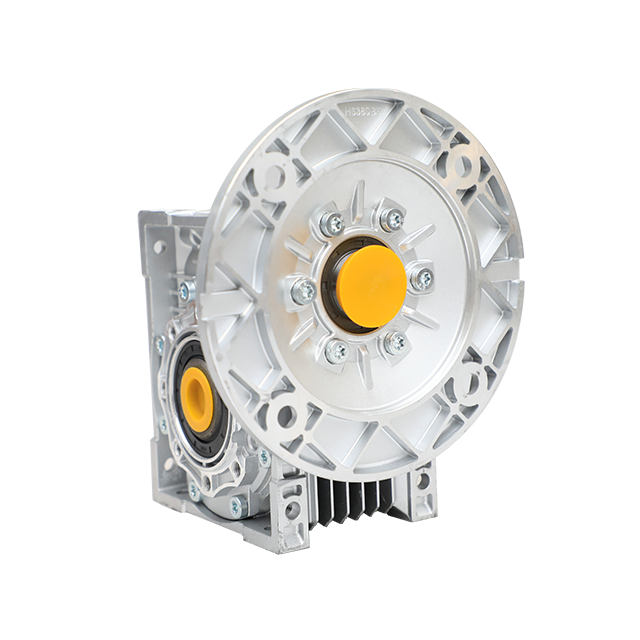
The NMRV Gearbox represents the modern, lightweight evolution of the traditional drive. This specific series of reducers is characterized by square-shaped, aluminum alloy die-cast housings. Transitioning from cast iron to aluminum offers several distinct floor-level advantages.
First, it drastically reduces the overall weight of the unit. This makes overhead installation easier and reduces the structural load on machinery frames. Second, the aluminum housing offers superior thermal conductivity. This helps dissipate the high heat generated by sliding friction much faster than iron. In addition, these units feature standardized IEC motor flanges, allowing for seamless integration with a wide variety of electric motors.
Because of their high modularity, these units are stocked globally in standardized ratios. Common configurations range from 7.5:1 up to 100:1. You will find them ubiquitous across multiple industries. In food processing and packaging machinery, their smooth, easy-to-clean aluminum surfaces and quiet operation are highly valued. In automation, the precise right-angle power transmission allows for compact robotic arm movements and automated guided vehicle drive systems.
Even with a solid understanding of gear mechanics, buyers frequently make sizing errors leading to catastrophic equipment failure and costly downtime. Avoiding these common pitfalls is essential for protecting your industrial investment.
The most critical mistake made when selecting a high-ratio unit is ignoring the thermal horsepower rating. Manufacturers provide two distinct ratings. The mechanical rating dictates how much physical torque the gears can handle before breaking. The thermal rating dictates how much continuous power the unit can transmit before the oil overheats and breaks down.
Because high ratios generate excessive sliding friction, the thermal rating is almost always lower than the mechanical rating. If a buyer sizes a 60:1 unit based solely on mechanical torque for a continuous round-the-clock application, the oil will boil. This destroys the oil seals and causes the bronze gear to melt against the steel screw. Always verify the application continuous power draw stays well below the thermal limits.
Lubrication acts as the lifeblood of any industrial drive. It is especially critical for sliding-friction mechanisms. Standard mineral oils working perfectly fine in helical gearboxes are wholly inadequate for the high-pressure environments found in right-angle screw sets.
Using the wrong oil leads to rapid bronze wear and premature failure. Engineering best practices dictate the use of high-quality synthetic lubricants, specifically Polyalkylene Glycol based oils. These synthetic oils offer a significantly lower coefficient of friction. This not only protects the internal components but marginally improves the overall mechanical efficiency and lowers the operating temperature.
Understanding the intricacies of reduction ratios is the master key to balancing your system velocity, torque, and safety features. Whether you need the space-saving right-angle design for a tight conveyor frame or the inherent self-locking capabilities for a lifting application, getting the math right ensures your machinery runs smoothly and safely.
Choosing the correct drive goes beyond simply matching the RPM. By evaluating thermal ratings, service factors, and the distinct benefits of modern aluminum NMRV housings, you will save significant capital and prevent unexpected factory downtime. Ready to find the ideal transmission unit for your next engineering project? Browse the extensive catalog of high-quality gear reducers at Huake Gearbox via https://www.huakegearbox.com to secure the exact ratio, standardized IEC flanges, and rugged performance your automated machinery demands.
Typically, a single-stage unit maxes out at a 100:1 ratio. The physical limitations of the gear teeth size and the housing prevent higher single-stage reductions. For higher mathematical values requiring massive speed drops, a double-stage gearbox combining two separate gear sets into one unit is required.
Yes. Because higher ratios rely on a much smaller lead angle on the input thread, they create significantly more sliding friction between the steel and the bronze. This increased friction lowers the overall mechanical efficiency and generates more thermal energy during operation.
Generally, a ratio of 50:1 or higher utilizing a lead angle of less than 5 degrees provides static self-locking. This means the load cannot back-drive the motor. However, external vibrations or sudden shocks can sometimes break this mechanical lock. Therefore, external motor brakes remain highly recommended for strict safety applications like elevators and hoists.
The mechanical reduction ratio is permanently fixed by the physical teeth on the internal gears. To change the final velocity later, you must completely replace the internal gear set, change the electric motor input speed, or install a Variable Frequency Drive to electronically control the motor RPM.
To increase the output twisting force, you must select a gearbox with a higher reduction ratio, assuming the input motor power remains constant. By stepping down the output velocity further, the mechanical advantage multiplies the available torque. However, you must always ensure the new torque demands do not exceed the mechanical rating of the bronze wheel.
The most common cause of failure is inadequate lubrication leading to thermal overload. When the wrong oil is used or oil levels drop, the extreme sliding friction generates excess heat. This causes the softer bronze wheel teeth to rapidly wear down, shear off, or gall against the hardened steel input shaft.


