
- All
- Product Name
- Product Keyword
- Product Model
- Product Summary
- Product Description
- Multi Field Search


Views: 0 Author: Site Editor Publish Time: 2026-10-15 Origin: Site


Does your machinery run too fast? Industrial motors require precise speed control to function optimally. A reliable power transmission mechanism solves this issue effortlessly. It bridges the gap between high-speed electric motors and the heavy-duty demands of driven equipment.
In this comprehensive engineering guide, you will learn exactly how these critical mechanical components work. Furthermore, we will explore the technical nuances of choosing the right drive unit to match the specific spatial and operational constraints of your facility.
In the realm of industrial power transmission, a Helical Gear Reducer is a specialized mechanical device engineered to decrease the rotational speed of an input motor while simultaneously multiplying the output torque. It belongs to the broader category of industrial gearboxes but is distinctly defined by its internal architecture featuring angled gear teeth.
The fundamental physics behind any speed-reducing mechanism rely on the principle of power conservation. A standard alternating current motor generates a specific amount of power measured in kilowatts. Reducing the rotational speed through calculated gear ratios naturally results in a proportional increase in rotational force. This mechanical transformation allows a standard, high-speed motor to drive heavy machinery that requires slow, forceful, and deliberate movements.
Global manufacturing is currently experiencing a massive shift toward energy-efficient automation. Plant managers face strict carbon footprint regulations and rising global energy costs. Consequently, the industry is rapidly phasing out legacy, inefficient drive systems. The modern manufacturing trend heavily favors precision-engineered helical units. These advanced systems integrate seamlessly with high-efficiency motors to drastically lower electrical consumption while maximizing output consistency. What sets this specific technology apart is the helix angle. Unlike traditional spur gears with teeth cut perfectly straight and parallel to the axis of rotation, helical gears feature teeth cut at a precise angle to the gear face. This angular design fundamentally transforms the mechanical dynamics of the entire power transmission system.
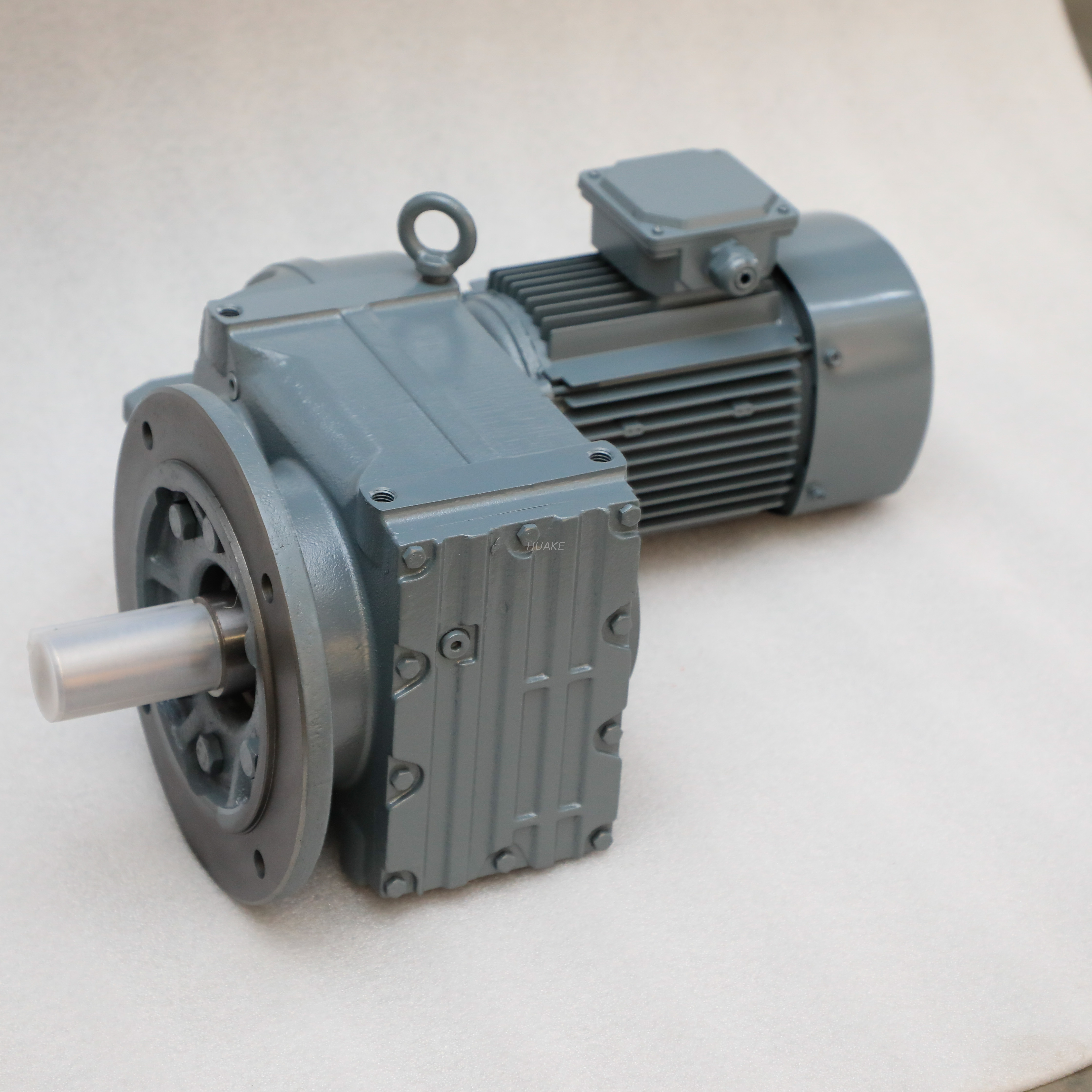
To comprehend why these units dominate heavy industry, we must examine the internal mechanics of how a Helical Gear Motor transfers kinetic energy under extreme stress.
Imagine a massive mining conveyor starting up under tons of raw ore. If the internal gears slam together instantly, the resulting shockwave could easily shatter the steel teeth. The core advantage of the helical design lies in its gradual engagement sequence. When two helical gears mesh, the contact between the teeth does not happen all at once. Contact begins at one end of the leading tooth and smoothly sweeps across the entire face as the gears rotate. This rolling action ensures that multiple teeth share the load at any given microsecond. Mechanical engineers refer to this crucial concept as a high contact ratio.
Because the teeth engage progressively rather than colliding abruptly, the transfer of torque is exceptionally fluid. This even force distribution minimizes the transient shock loads that typically cause premature mechanical wear. Consequently, the ambient vibration levels are drastically reduced. For plant operators, this translates to a quieter operational environment and significantly less structural fatigue on the surrounding machinery components.
In contrast to these benefits, the laws of physics dictate that the angled cut of the teeth introduces a challenging variable known as axial thrust. As the gears push against each other to transfer rotational force, the helix angle causes a portion of that energy to be directed sideways along the shaft axis. Manufacturers engineer internal solutions to ensure the gearbox does not destroy itself under this lateral pressure. Modern designs typically incorporate heavy-duty tapered roller bearings to absorb these forces safely. Alternatively, highly specialized heavy-industry units utilize double-helical herringbone gears. In these designs, two mirrored angles cancel out the axial thrust entirely, albeit at a higher manufacturing cost.
Industrial environments vary wildly, ranging from cramped indoor manufacturing floors to sprawling, exposed mining operations. Manufacturers produce several distinct architectural configurations to accommodate these diverse spatial and load requirements.
The Inline Helical Gearbox is characterized by its concentric design. In this specific layout, the input shaft connected to the motor and the output shaft connected to the driven machine align on the exact same rotational axis. The primary benefit here is a highly compact, cylindrical footprint. It remains the preferred choice for fluid pumps, fans, and mixers where radial space is strictly limited, and the drive package needs to protrude straight out from the equipment.
Conversely, a Parallel Shaft Reducer operates with the input and output shafts positioned parallel to one another rather than in a straight line. This offset design allows multiple gear stages to be stacked within a flat, rectangular cast-iron housing. This configuration is renowned for handling exceptionally high torque loads. For instance, industrial-grade F-Series parallel shaft units engineered for heavy-duty conveying systems frequently deliver output torque ranging from 130 Nm up to an impressive 18,000 Nm. They support power inputs from 0.12 kW to 200 kW, achieving gear ratios between 3.77 and 277.2 in a single compact housing. Furthermore, its narrow profile makes it structurally ideal for tight, side-by-side mounting in continuous processing lines and overhead crane assemblies.
When a facility layout requires the power transmission to navigate a 90-degree corner, a bevel-helical combination is deployed. This robust unit utilizes a set of spiral bevel gears at the initial input stage to redirect the power at a right angle. Standard helical stages follow to achieve the final speed reduction. It seamlessly combines high transmission efficiency with spatial flexibility, making it highly suitable for large conveyor belt drives and heavy-duty agitators.
For procurement managers and mechanical engineers, finalizing a gearbox specification requires an objective analysis of its inherent benefits and limitations relative to the specific application demands.
These gears rely primarily on rolling contact rather than sliding friction. This minimizes internal heat generation. As a result, these reducers frequently achieve efficiency ratings between 95 percent and 98 percent per gear stage. Plant managers can rest assured that very little electrical power is wasted as thermal energy.
The sweeping tooth engagement virtually eliminates the whining or clanking noise heavily associated with straight-cut gears. In modern facilities enforcing strict occupational safety standards, this acoustic dampening provides a critical compliance advantage.
Because multiple teeth are in contact simultaneously, the mechanical stress is distributed over a much larger surface area. This physical trait allows the unit to transmit immense torque and survive moderate shock loads without suffering catastrophic tooth shear.
As detailed earlier, the helix angle inherently generates axial thrust, necessitating the inclusion of robust internal bearings. Premature failure is guaranteed if a buyer inadvertently selects a unit with undersized bearings for their specific load profile. In practice, engineers must always verify the manufacturer axial load ratings against the actual operating data of the machine before issuing a purchase order.
The precision CNC machining required to cut angled teeth makes these units more expensive to manufacture than standard spur gearboxes. However, seasoned buyers evaluate the Total Cost of Ownership. The long-term energy savings gained from superior efficiency, coupled with an extended operational lifespan, typically offset the initial purchase premium within the first two years of operation.
To solidify a purchasing decision, comparing this technology against another common Speed Reducer mechanism provides valuable context for industrial buyers.
| Feature | Helical Gearbox | Spur Gearbox | Worm Gear Reducer |
|---|---|---|---|
| Mechanical Efficiency | 95% - 98% per stage | 90% - 95% per stage | 50% - 85% overall |
| Noise Level | Very Low | High (Prone to whining) | Low |
| Axial Thrust Generation | Yes (Requires robust bearings) | No | Yes |
| Load & Torque Capacity | Extremely High | Moderate | Moderate to High |
| Thermal Dissipation | Excellent | Good | Poor (Generates high heat) |
Spur gears feature straight teeth cut parallel to the shaft. When they mesh, the entire face of the tooth makes contact instantly. This causes a micro-collision that generates significant noise and mechanical stress. While spur gears are cheaper to produce and do not generate axial thrust, they are generally deemed unsuitable for high-speed or heavy-duty industrial applications due to lower durability. Helical technology represents the undisputed upgrade for smooth, long-term reliability.
Worm gearboxes utilize a screw-like worm driving a perpendicular mating wheel. They are incredibly compact and offer massive reduction ratios within a single stage. Additionally, worm gears can be self-locking, meaning the physical load cannot drive the motor backward. The fatal flaw of worm gears is thermal efficiency. They rely heavily on sliding friction, which generates excessive heat and can plummet efficiency down to 50 percent. If low energy consumption and continuous operation are priorities, helical gears are vastly superior.
Because of their unwavering reliability and high efficiency, these specific gearboxes serve as the mechanical backbone for numerous heavy industries.
In mining, logistics, and bulk material handling, conveyor belts must run continuously under fluctuating, heavy loads. The parallel shaft configuration is frequently chosen here. Its flat profile allows it to be mounted directly alongside the conveyor frame. This provides massive, steady torque to move tons of aggregate without wasting electrical power.
Chemical processing and municipal wastewater treatment plants require massive paddles to stir highly viscous liquids. An inline unit mounted vertically provides the steady, high-torque, low-vibration power necessary to maintain consistent mixing vortexes without stressing the motor bearings.
In the plastics manufacturing and recycling sectors, machinery must force solid materials through tight dies or violently crush them into smaller fragments. These brutal applications generate extreme, unpredictable shock loads. Heavy-duty helical units equipped with reinforced cast-iron housings and high-capacity bearings are uniquely capable of surviving these punishing operating conditions.
Selecting the correct drive equipment requires a systematic, empirical approach. A mismatch between the motor, the gearbox, and the application inevitably leads to premature mechanical failure, excessive energy consumption, or unnecessary capital expenditure. Evaluating mechanical parameters, spatial constraints, and environmental conditions is non-negotiable for decision-makers.
The fundamental purpose of any reducer is to convert high-speed, low-torque motor rotation into low-speed, high-torque output. Relying on guesswork for these metrics leads to undersized units that shatter or oversized units that waste valuable space and capital. First, determine the required gear ratio by dividing the input speed by the desired output speed of the driven machine. Next, calculate the required output torque. Engineers must account for starting torque, which can easily spike to 300 percent of the running torque, along with peak operational loads. Always factor in the mechanical efficiency of the gear stages when finalizing the torque demands.
Once the mechanical performance metrics are locked in, physical space and integration constraints dictate the geometry of the housing. Foot-mounted designs feature a solid cast base with pre-drilled holes. This is ideal for securing the unit directly to a structural steel frame, providing maximum stability for high-vibration equipment. Flange-mounted units bolt directly onto the driven machine housing to ensure perfect shaft alignment. Shaft-mounted designs feature a hollow output shaft that slides directly over the driven machine solid shaft, secured with a shrink disc or keyway. This highly popular method saves significant space and completely eliminates the need for flexible couplings.
Mathematical torque calculations assume ideal, uniform operating conditions. In reality, equipment faces shock loads, frequent start-stop cycles, and continuous operation. Engineers apply a Service Factor multiplier to account for these harsh realities. This vital safety margin ensures the gearbox is physically robust enough to survive its intended environment. A light conveyor running eight hours a day might require a Service Factor of 1.0. However, a rock crusher running continuously under heavy shock loads requires a Service Factor of 2.0 or higher.
Additionally, buyers must rigorously evaluate radial loads. If the output shaft connects to the machine via a chain, V-belt, or pinion gear, it creates a severe perpendicular force on the shaft. The internal bearings must be explicitly rated to handle this radial load. Otherwise, the shaft will deflect, leading to immediate oil seal leaks and eventual bearing collapse.
A gearbox is only as reliable as its lubrication and sealing system. Maintaining a microscopic elastohydrodynamic oil film between the metal teeth is critical to preventing catastrophic wear. High-quality mineral oils are sufficient for standard applications. However, fully synthetic polyalphaolefin oils are strongly recommended if the unit operates in extreme ambient temperatures or under continuous heavy loads. Synthetic oils maintain their viscosity across a broader temperature spectrum and significantly extend the interval between required oil changes.
Industrial environments are rarely clean. If the equipment is deployed in a dusty cement plant, heavy-duty labyrinth seals or dual-lip FKM seals are absolutely necessary to prevent abrasive particulate from destroying the internal bearings. For food and beverage processing, the unit must feature IP66-rated washdown protection and utilize certified food-grade lubricants.
A precision-engineered helical gear reducer provides unparalleled efficiency and reliability for demanding industrial applications. By utilizing progressive tooth engagement, these units deliver exceptionally smooth operation while effortlessly handling massive torque loads.
While the initial capital costs may be slightly higher than legacy spur or worm drives, the dramatic energy savings and extended operational lifespan quickly offset this premium. Their proven durability in harsh environments makes them a highly cost-effective, long-term choice for modern manufacturing and processing facilities.
When you are ready to upgrade your power transmission systems, explore the complete range of industrial drive solutions at Huake Gearbox. Contact our sales engineering team for a comprehensive technical consultation, or browse our extensive catalog to find the exact equipment needed to keep your production moving efficiently.
Yes, standard helical gearboxes are inherently bidirectional and can operate efficiently in both clockwise and counterclockwise directions. However, because the angled teeth naturally generate axial thrust forces, the internal thrust bearings are specifically arranged to absorb this load. If an application requires frequent, heavy-load reversing, engineers must verify with the manufacturer that the bearing configuration is symmetrical and capable of handling maximum thrust in both directions without causing excessive shaft end-play.
The stark efficiency difference comes down to the fundamental physics of tooth engagement. A helical unit utilizes a smooth rolling action as the gear teeth mesh, which generates minimal sliding friction. This allows them to achieve mechanical efficiencies between 95 percent and 98 percent per stage. In contrast, worm gears rely on a heavy sliding action between the worm shaft and the bronze wheel. This sliding creates significant friction and thermal energy, resulting in heavy power losses. Worm gear efficiencies typically range from 50 percent to 85 percent, meaning they consume considerably more electricity to deliver the exact same output torque.
When properly sized according to accurate service factors and maintained rigorously, an industrial-grade unit can operate reliably for 10 to 20 years. The limiting factor is rarely the hardened steel gears themselves, but rather the internal rolling-element bearings and elastomeric oil seals. Bearing life is calculated using the L10h standard, which typically targets 10,000 to 100,000 operational hours depending on the applied load. Adhering to strict oil analysis protocols, regularly replacing breather valves, and preventing overhung load limits from being exceeded are the most effective practical ways to maximize the unit lifespan.
Mechanical noise in a gearbox is primarily caused by transmission error and the sudden, violent impact of gear teeth engaging. If you are currently using a spur gear system, upgrading to a helical design is the most effective permanent solution. The angled teeth ensure a gradual, sweeping engagement, resulting in a higher contact ratio where multiple teeth share the load simultaneously. This virtually eliminates the harsh vibration and high-pitched whining noise. Additionally, verifying that the gear mesh is adequately lubricated with the correct viscosity synthetic oil will further dampen acoustic resonance.
Calculating the gear ratio is a straightforward mathematical process. You divide the number of teeth on the driven gear by the number of teeth on the driving gear. For multi-stage gearboxes, you calculate the ratio for each individual gear set and multiply them together to find the total overall reduction ratio. Alternatively, from an operational standpoint, you can divide the motor input speed by the final output speed of the gearbox shaft to determine the effective working ratio.
Overheating is typically caused by a combination of improper lubrication, excessive mechanical loading, or poor environmental conditions. Using the wrong oil viscosity or operating with low oil levels destroys the protective elastohydrodynamic film, leading to metal-on-metal friction. Additionally, if the gearbox is subjected to torque loads or radial forces that exceed its design specifications, the internal bearings will generate massive amounts of thermal energy. Ensuring proper sizing during the selection phase and adhering to strict maintenance schedules are the best defenses against thermal failure.


