
- All
- Product Name
- Product Keyword
- Product Model
- Product Summary
- Product Description
- Multi Field Search


Views: 0 Author: Site Editor Publish Time: 2026-10-19 Origin: Site


Electric motors naturally spin incredibly fast. Often, they rotate far too rapidly for heavy lifting or precise automated tasks. Without a reliable mechanism to control this raw rotational speed, automated systems would essentially tear themselves apart. They simply lack the brute strength required to move substantial loads. In the field, industrial equipment demands immense power delivered at much slower, deliberate paces.
This is where a high-quality gear reducer steps in to bridge the mechanical gap. In this comprehensive guide, we will break down exactly how these critical mechanisms operate, explore their internal anatomy, and help you determine which configuration is best suited for your specific operational demands.
At its core, this mechanical device—frequently referred to as a speed reducer or an enclosed drive—is a vital power transmission component. It is securely positioned between a prime mover, such as an alternating current electric motor, and a piece of driven machinery. Its primary function is to alter the output of the motor to match the specific, often rigorous, requirements of the equipment it powers. Standard electric motors are generally designed to operate at high rotational speeds because this configuration is highly efficient and cost-effective to manufacture. However, most practical field equipment requires sluggish speeds paired with massive force to function without stalling. This ranges from sprawling conveyor belts to heavy-lifting mining cranes.
To better grasp this concept, consider the everyday analogy of riding a multi-speed bicycle. When a cyclist approaches a steep incline, pedaling in a high gear is nearly impossible. It demands too much immediate force from the rider. By shifting into a lower gear, the rider must pedal much faster, but the rear wheel turns slower with significantly more driving force. The industrial unit performs this exact function for automated machinery. It acts as a buffer and an amplifier, ensuring the attached machinery operates at the correct rhythm and force without overloading the facility electrical system.
To understand the inner workings of these systems, engineers must examine the fundamental physics of interlocking gear teeth and the principles of mechanical advantage. The entire operation relies on the law of conservation of energy. In a closed mechanical system, power equals torque multiplied by rotational speed. Because the power coming from the connected motor remains relatively constant, altering the speed directly and inversely alters the torque.
Specifically, the mechanical transformation occurs between two primary points within the casing. The input shaft connects directly to the prime mover. It rotates at a blistering speed but carries relatively low rotational force. Connected to the driven machine, the output shaft is driven by a larger gear inside the casing. Consequently, it rotates at a noticeably slower speed but delivers significantly higher, load-moving torque.
The extent to which the speed is altered is determined by the internal gear ratio. Engineers calculate this metric simply by dividing the number of teeth on the output gear by the number of teeth on the input gear. For example, if the input pinion has 10 teeth and the output gear features 100 teeth, the ratio is 10:1. The motor must complete ten full revolutions to turn the output shaft exactly one time.
This mathematical relationship forms the bedrock of automated force generation. If an engineer applies a 10:1 ratio to a motor spinning at 1,000 revolutions per minute with 10 Nm of torque, the output shaft will theoretically spin at 100 revolutions per minute and deliver 100 Nm of torque. In real-world factory applications, physical friction slightly reduces the final output. However, the principle remains the definitive method for generating mechanical muscle.
| Gear Ratio | Motor Input Speed | Motor Input Torque | Reducer Output Speed | Theoretical Output Torque |
|---|---|---|---|---|
| 5:1 | 1500 RPM | 20 Nm | 300 RPM | 100 Nm |
| 10:1 | 1500 RPM | 20 Nm | 150 RPM | 200 Nm |
| 25:1 | 1500 RPM | 20 Nm | 60 RPM | 500 Nm |
| 50:1 | 1500 RPM | 20 Nm | 30 RPM | 1000 Nm |
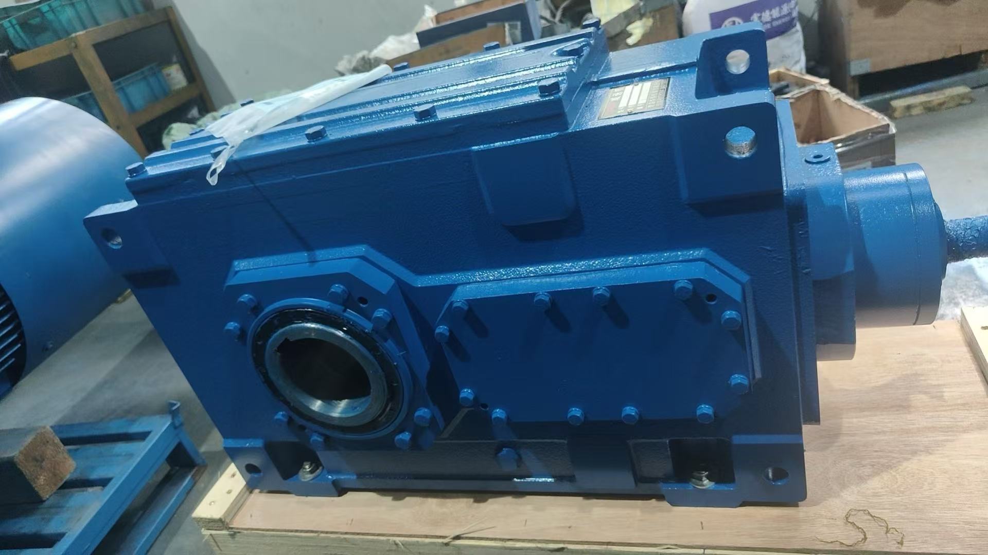
Imagine standing on a bustling factory floor. The rhythmic hum you hear is largely dictated by the precision components hidden within the cast-iron shell of an industrial gearbox. These are complex assemblies engineered to operate relentlessly under extreme stress.
Different mechanical environments require distinct methods of power transmission. Engineers must select specific topologies based on spatial limitations, torque demands, and strict efficiency targets.
A helical gear reducer utilizes gears with teeth cut at a precise angle to the face of the gear. When two teeth in this system engage, the contact starts seamlessly at one end of the tooth and gradually spreads across the face as the gears rotate. This gradual, rolling engagement allows them to operate much more smoothly and quietly than older, standard spur gears. For heavy-duty industrial applications, premium units like the HB series standard industrial gearboxes leverage modular designs to achieve massive outputs. In the field, we frequently see these advanced units delivering torque outputs up to 470,000 Nm with transmission ratios spanning from 1.25 to 450. They effortlessly handle incredibly high loads while maintaining efficiency ratings that routinely exceed 95 percent, making them the gold standard for continuous manufacturing operations.
This classic configuration consists of a threaded worm screw that meshes perpendicularly with a toothed worm wheel. The primary advantage here is the ability to achieve massive speed reductions within a remarkably compact footprint. Because the transmission relies heavily on sliding friction rather than rolling friction, they generate more heat and are inherently less efficient. However, they offer a highly sought-after safety feature known as self-locking. In many setups, the wheel simply cannot drive the worm screw backward. This makes them perfect for hoisting, elevators, or lifting applications where preventing a reverse free-fall is non-negotiable.
Planetary models feature a central sun gear surrounded by multiple planet gears, all snugly enclosed within a stationary outer ring gear. As the sun gear rotates, it drives the planets, which roll along the inside of the ring. This ingenious configuration distributes the mechanical stress evenly across multiple contact points simultaneously. Consequently, planetary units offer exceptionally high torque density in a surprisingly lightweight package. They are heavily favored in precision-critical tasks, such as robotic arm articulation and aerospace engineering, where low mechanical backlash and exact positioning are paramount.
Easily identified by their unique cone-shaped gears, bevel reducers are explicitly utilized when the direction of shaft rotation needs to be redirected, typically by exactly 90 degrees. While they do provide speed reduction, their primary mechanical value lies in rerouting power flow in tight spaces. You will frequently find them in automotive differentials, mining conveyors, and any facility where the motor must be mounted flush against a wall or at a right angle to the driven equipment.
Integrating these devices into a mechanical drive system is not merely an optional upgrade. It is a fundamental requirement for safe industrial operation. The benefits extend far beyond simply slowing things down.
Beyond speed alteration, the most critical benefit is torque multiplication. By throttling the speed of the prime mover, the unit amplifies the output force. This allows facilities to utilize smaller, highly efficient electric motors to move incredibly heavy loads. Without this multiplication, machines would require massive, financially impractical motors just to generate the necessary starting inertia.
Furthermore, many industrial processes require exact operating speeds to function correctly. Picture a sprawling bottling plant. The conveyor belt must move at a highly specific, synchronized pace to ensure bottles are filled, capped, and labeled without spilling. The reducer provides the exact rhythm required for this delicate ballet. It also acts as a mechanical shock absorber. When a motor attempts to start a heavy load directly, the sudden resistance can cause massive electrical spikes, leading to burnt-out windings. The gearbox helps the motor spin up smoothly, matching the inertia of the motor to the heavy load.
As global manufacturing shifts toward smart automation, the landscape of mechanical power transmission is evolving rapidly. Recent industry analyses highlight a massive surge in demand for intelligent motion control. Facilities are no longer satisfied with purely mechanical components. They demand predictive maintenance capabilities. Modern drive units are increasingly outfitted with integrated IoT sensors that continuously monitor vibration signatures, acoustic anomalies, and oil temperatures in real-time. This allows maintenance engineers to predict bearing failures weeks before they happen, drastically reducing catastrophic unplanned downtime.
In addition, stringent global energy regulations are forcing a shift in drive topologies. There is a noticeable market migration away from low-efficiency worm gears in continuous-duty applications. Industries are moving heavily toward highly efficient helical and bevel-helical designs. Plant managers realize that the slightly higher upfront cost of a premium, high-efficiency gearbox is quickly offset by years of significantly reduced electrical consumption.
Selecting the correct mechanical components for an automated system is a critical engineering decision. A mismatched unit leads directly to sheared teeth, excessive downtime, and significant financial loss. The selection process requires a systematic approach, evaluating mathematical requirements, environmental factors, and cost-efficiency variables.
Step 1: Calculate Your Mechanical Requirements
The first step is establishing the precise mathematical demands of your driven equipment. You must determine the desired output speed by dividing the motor input speed by the necessary gear ratio. Next, calculate the required output torque. This is the absolute most critical metric. If the torque demand of the load exceeds the physical capacity of the internal gears, catastrophic failure is imminent.
Step 2: Apply a Service Factor
Engineers must apply a service factor to their calculations. Since real-world loads are rarely perfectly smooth, the service factor acts as a safety multiplier. A rock crusher experiencing violent shock loads might require a service factor of 2.0, whereas a smoothly running liquid agitator may only need 1.0.
Step 3: Consider the Operating Environment
The physical surroundings drastically influence the external build of the unit. High ambient heat requires synthetic lubricants and active cooling fans to prevent oil breakdown. Conversely, freezing environments demand low-viscosity oils. If the unit operates in a dusty cement plant, severe-duty labyrinth seals are mandatory to prevent abrasive grit from destroying the bearings. For food processing facilities involving caustic washdowns, specialized epoxy coatings become absolute necessities.
Efficiency vs. Cost: A Comparative Analysis
Budget constraints must always be balanced against long-term operational efficiency. Understanding this cost-to-benefit ratio is essential for project procurement.
| Gear Topology | Average Efficiency | Initial Cost | Best Suited For Field Applications |
|---|---|---|---|
| Helical | 95% - 98% | Higher | Continuous heavy-duty manufacturing, high-efficiency needs, large torque outputs. |
| Worm | 50% - 85% | Lower | Space-constrained areas, applications requiring self-locking features. |
| Planetary | 90% - 97% | Premium | Precision robotics, heavy mobile equipment, high torque density requirements. |
| Bevel | 94% - 98% | Moderate-High | Right-angle shaft orientation, tight corner installations. |
Mastering the concepts behind mechanical power control is vital for anyone involved in industrial engineering or facility maintenance. By effectively converting high-speed motor rotation into usable, high-torque power, these devices form the muscular foundation of modern automation.
Precise gear transmission ensures that complex industrial systems run smoothly, safely, and efficiently. Whether you are designing a simple warehouse conveyor or engineering a state-of-the-art robotic assembly line, taking the time to calculate loads, assess the environment, and select the perfect topology guarantees years of relentless operation. Selecting the perfect unit dictates the lifespan of your entire production line. For robust, high-torque solutions, explore the comprehensive configurations available at Huake Gearbox to find the exact match for your demanding operational requirements.
Yes, under specific mechanical conditions, a gear train can be configured to increase speed. If you apply rotational power to the slow-speed shaft, the high-speed shaft will rotate much faster. In this scenario, the device acts as a speed increaser or an overdrive unit. However, the fundamental laws of physics still apply. Just as reducing speed increases torque, increasing speed proportionally sacrifices torque. This configuration is highly common in wind turbines, where the slow rotation of the massive blades must be multiplied significantly to spin the internal generator fast enough to produce electricity. Note that self-locking worm gears cannot be back-driven in this manner.
In industrial terminology, these terms are frequently used interchangeably, but there is a distinct technical difference. A gearbox is a broad, umbrella term referring to any mechanical casing that contains a series of enclosed gears. It can be designed to reduce speed, increase speed, change rotational direction, or transfer power at a one-to-one ratio. A gear reducer, on the other hand, is a highly specific type of gearbox explicitly engineered to take high-speed, low-torque input and convert it into low-speed, high-torque output. Therefore, all gear reducers are gearboxes, but not all gearboxes are gear reducers.
The discrepancy in mechanical efficiency comes down to the fundamental physics of how the teeth interact. In a helical setup, the angled teeth are designed to engage gradually and roll against one another. This rolling action creates very little sliding friction, meaning minimal kinetic energy is lost as heat, allowing them to routinely achieve efficiencies of 95 to 98 percent. Conversely, a worm mechanism consists of a threaded screw that continuously rubs and slides against the teeth of a wheel. This inherent sliding friction generates a substantial amount of heat, which directly wastes energy and reduces the unit efficiency to anywhere between 50 and 85 percent.
Maintenance schedules are highly dependent on the operational environment and the duty cycle, but a baseline protocol exists for most field applications. Visual inspections should occur weekly to check for external oil leaks and to monitor for unusual acoustic changes. Oil levels must be verified monthly. For standard operating conditions, a complete oil change is generally recommended every 2,500 to 5,000 operating hours, or at least once a year. In severe environments involving high heat or heavy shock loads, this interval should be halved to ensure optimal lubrication.
Mechanical components rarely fail without exhibiting clear warning signs. The most immediate symptom is an acoustic change. Excessive grinding, whining, or clanking noises indicate that the teeth are wearing unevenly or bearings are failing. Unusual vibrations transmitted through the housing suggest internal misalignment or shaft deflection. Thermal changes are also a primary indicator. If the exterior housing becomes excessively hot to the touch, it usually points to a breakdown in lubrication. Finally, visual cues such as oil pooling beneath the unit indicate compromised seals, leaving internal components vulnerable to friction and external contamination.
Calculating the gear ratio is a straightforward mathematical process. You simply divide the number of teeth on the driven gear by the number of teeth on the driving gear. For a multi-stage gearbox, you calculate the ratio of each individual gear set and multiply them together to find the total reduction ratio. Alternatively, if you know the input speed of the motor and the final output speed of the shaft, you can divide the input speed by the output speed to determine the exact working ratio of the unit.
Overheating is typically a symptom of severe internal friction or environmental factors. The most common culprit is improper lubrication. Using the wrong oil viscosity, having too little oil, or even overfilling the unit can cause excessive heat buildup. Mechanical issues such as misaligned shafts, worn-out bearings, or operating the unit well beyond its rated torque capacity will also generate dangerous levels of thermal energy. Additionally, if the unit is installed in an area with poor ventilation or high ambient temperatures without proper cooling fans, it will struggle to dissipate operational heat effectively.


