
- All
- Product Name
- Product Keyword
- Product Model
- Product Summary
- Product Description
- Multi Field Search


Views: 0 Author: Site Editor Publish Time: 2026-10-15 Origin: Site


Why do industrial machines so often rely on helical gearing? A Helical Gear Reducer combines efficient power transmission, smooth engagement and flexible configurations for suitable applications. In this article, you’ll learn why these advantages matter and how selection, installation and maintenance influence performance.
Every gearbox loses some input power through gearing, bearings, seals and lubricant movement. Lower losses leave more power available for useful work. However, individual-stage efficiency differs from complete gearbox efficiency. Additional stages introduce additional losses. Compare documented performance at the intended speed, load and temperature instead of assuming one universal efficiency value.
Helical teeth engage progressively as the gears rotate. Their overlapping contact helps transfer load through successive teeth more smoothly. This characteristic supports machinery requiring steady motion. Manufacturing accuracy, alignment and loading still influence the result. Smooth engagement cannot compensate for an unsuitable coupling, damaged bearing or poorly installed drive.
Overlapping tooth contact contributes to load distribution within the gear mesh. This helps explain helical gearing’s usefulness in industrial transmission. Yet allowable torque depends on the complete design. Gear dimensions, materials, heat treatment and bearing support all matter. Confirm the selected unit’s rating rather than estimating capacity from tooth geometry alone.
Progressive engagement can reduce excitation compared with comparable spur gear arrangements. This makes helical gearing attractive where operating noise matters. Actual sound levels also depend on speed, gear quality and installation. Evaluate noise under representative loading. A quiet unloaded demonstration may not reflect the behavior of the complete production machine.
Long operating hours make transmission losses and thermal behavior especially relevant. A reducer must transmit the required torque while controlling operating temperature. Mechanical capacity alone does not establish continuous-duty suitability. Review the load profile, ambient conditions and cooling arrangement. Stable operation requires the selected unit to satisfy both mechanical and thermal requirements.
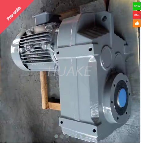
Helical gearing appears in inline, parallel-shaft and bevel-helical arrangements. These configurations help designers match the machine’s available space and shaft orientation. HUAKE’s FA107 F Series Helical Gear Motor uses a parallel-shaft arrangement and modular motor matching. Confirm the exact configuration through its current drawing before designing connections.
Tip: Compare efficiency and temperature performance at your actual operating point before selecting a reducer.
A helical gear reducer for conveyors matches motor speed to the required material movement. Selection must include loaded starts and changing conveyor resistance. Pulley or sprocket connections can also impose radial shaft loads. Provide these details during sizing. A steady running load does not describe every demand placed on the reducer.
A helical gear reducer for mixers must accommodate the material’s changing resistance. Viscosity, batch composition and startup conditions can influence torque demand. The mixer shaft may also introduce forces requiring additional bearing support. Review these loads separately from transmitted torque. Suitable selection begins with the mixing process rather than motor power alone.
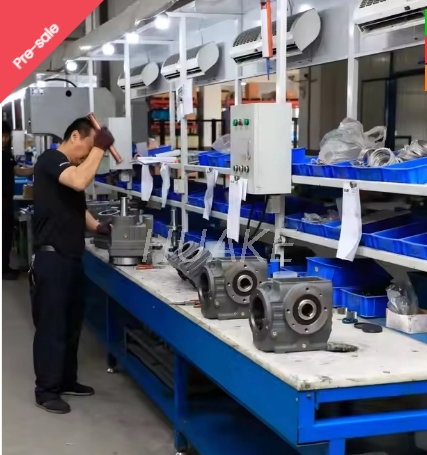
Packaging machinery often combines repeated starts, stops and speed changes. Smooth transmission supports predictable machine movement during these cycles. HUAKE’s FAF57 F Series Gear Motor lists automation and material handling among its applications. Confirm the selected ratio and duty conditions. Precision positioning additionally requires application-specific backlash and control assessment.
Heavy processing can involve substantial torque, shocks and variable loading. Dust, ventilation and ambient temperature can add further constraints. Manufacturer literature identifies conveyors, mixers and crushers among industrial helical-drive applications. However, a heavy-duty description cannot replace sizing calculations. Review peak demands and thermal limits for the particular machine.
Compare helical and worm reducers using the required ratio, layout and operating hours. Worm-drive efficiency varies according to geometry and operating conditions. Continuous operation can make those differences more significant. Holding behavior needs separate confirmation. Do not assume a worm reducer provides reliable self-locking under every load or operating condition.
Spur and helical gearing introduce different design considerations. Helical teeth provide progressive engagement but also generate axial forces. Bearings and housing arrangements must accommodate those forces. Evaluate noise, speed, loading and installation together. The complete gearbox design determines suitability rather than a single advantage associated with its gear type.
An inline arrangement suits different shaft relationships from a right-angle drive. Bevel-helical and hypoid configurations introduce additional gearing characteristics requiring assessment. Confirm the actual architecture before comparing performance. Product titles sometimes combine several reducer terms. Use technical drawings and model-specific documentation to establish what the proposed unit contains.
Planetary arrangements may offer useful packaging or torque-density characteristics for certain machines. Helical reducers offer another practical route for industrial speed reduction. Compare space, backlash, loading and maintenance requirements together. Neither architecture guarantees the best outcome across every application. Select the complete drive according to the machine’s defined operating priorities.
Start by defining the driven machine’s required speed and torque. Output speed approximately equals input speed divided by the reduction ratio. Available output torque also depends on transmission efficiency. For practical helical gear reducer selection, check the manufacturer’s ratings alongside calculations. Increasing the ratio does not increase available output power.
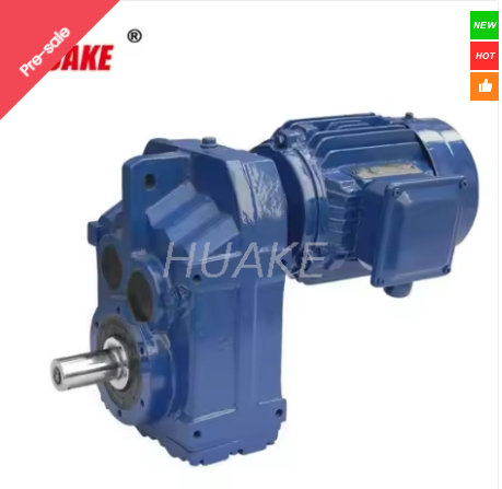
Describe operating hours, starts per hour, reversals and load variation. Apply the chosen manufacturer’s service-factor method to those conditions. Different selection systems may use different assumptions. HUAKE’s F127 Gear Motor is presented for demanding industrial transmission. Confirm model-specific capacity and peak-load suitability before selecting it.
Thermal rating addresses heat generation and the ability to dissipate it. High ambient temperatures or restricted airflow can change permissible operation. Mounting position and lubrication also influence the assessment. A mechanically adequate reducer may still require cooling or another configuration. Confirm thermal suitability at the intended speed, load and operating duration.
Check output-shaft radial and axial loads alongside transmitted torque. Provide pulley diameters, sprocket positions and connection dimensions where relevant. Confirm mounting position and motor interface before ordering. Variable-speed operation also changes the operating envelope. Evaluate the motor, reducer and driven machine together across the required speed range.
| Selection factor | Information to provide | Why it matters |
|---|---|---|
| Output requirements | Required speed and torque | Establishes ratio and capacity needs |
| Load profile | Startup, peak and running loads | Supports duty and service-factor assessment |
| Operating schedule | Daily hours, starts and reversals | Identifies repeated and continuous demands |
| Environment | Temperature, airflow and contamination | Influences thermal and protection requirements |
| Shaft connections | Radial loads, axial loads and dimensions | Determines bearing and interface suitability |
| Installation | Mounting position and available space | Guides configuration and lubrication planning |
Tip: Send the load profile and shaft-connection details alongside the required motor power.
Alignment and mounting influence bearings, couplings and vibration. Follow the specified tolerances rather than correcting misalignment through excessive fastening force. Check the supporting base and connection details before startup. Reinspect the assembly during commissioning. Record baseline behavior so later changes can be compared against the original operating condition.
Lubricant selection requires the correct type, viscosity and compatibility. Oil quantity must also suit the mounting position. Follow the reducer manufacturer’s current instructions for filling and inspection. Avoid assuming a larger quantity provides better protection. Use the specified replacement procedure and investigate contamination or unusual lubricant changes.
Establish baseline readings under representative loading after commissioning. Record operating speed and ambient conditions alongside them. Investigate changes before increasing output or modifying settings. Trends can help identify overload, lubrication issues or developing wear. Interpret measurements together rather than treating one temperature reading as a complete diagnosis.
Tip: Correct lubrication and alignment help preserve performance; they cannot resolve an undersized drive.
Compare alternatives delivering the same output speed and useful load. Include the operating schedule and variations in demand. Separate gearbox efficiency from motor and overall system efficiency. HUAKE’s helical gear reducer range provides options for further selection review. Request performance information for the proposed configuration rather than comparing general efficiency labels.
Purchase price represents only part of ownership cost. Include electricity, lubrication, maintenance and replacement work in the comparison. Account for installation changes and spare-parts requirements where relevant. Annual energy differences depend on operating hours and loading. Calculate savings using documented conditions instead of presenting a guaranteed payback period.
Ask for evidence involving comparable loading, operating hours and environmental conditions. Review maintenance history and reasons for previous failures. General durability claims provide limited information without context. Assess downtime alongside energy use and service requirements. A suitable reducer should support dependable operation throughout the intended maintenance and production schedule.
Identify the actual gear stages, shaft arrangement and model configuration. Request the current drawing and model-specific rating information. Some product pages combine family ranges with individual model descriptions. Resolve those differences before approving a proposal. The quotation should clearly identify the supplied ratio, motor arrangement and mounting position.
Confirm output torque, speed, duty cycle and thermal suitability together. Ask which conditions support quoted efficiency or noise values. Verify peak-load limits separately where the application requires them. Braking and backdriving behavior also need specific assessment. Avoid treating a reducer’s general description as proof of load-holding capability.
Define checks for rotation, output speed, loading, temperature, vibration and leakage. Confirm lubrication and mounting requirements before starting the machine. Review documentation and maintenance access during handover. Agree on technical support responsibilities for commissioning. Clear acceptance conditions make the completed installation easier to evaluate and maintain.
Tip: Record the approved configuration and operating conditions in the purchase specification.
A Helical Gear Reducer supports efficient transmission, smooth operation and adaptable layouts in industrial drive systems. Correct sizing, thermal assessment, installation and lubrication help maintain reliable performance. HUAKE offers modular F series gear motors, supported by customization, technical assistance and after-sales service. These options help manufacturers match drive configurations to conveyor, mixer and production machinery requirements.
A: A Helical Gear Reducer offers efficient transmission and smooth engagement.
A: Match the Helical Gear Reducer to torque, speed, duty and thermal requirements.
A: Helical Gear Reducer costs vary by capacity, configuration and customization.
A: Transmission efficiency varies by design, ratio and operating conditions.
A: Industrial drives may overheat from overload, unsuitable lubrication or inadequate cooling.


