
- All
- Product Name
- Product Keyword
- Product Model
- Product Summary
- Product Description
- Multi Field Search


Views: 0 Author: Site Editor Publish Time: 2026-10-18 Origin: Site


Do you need high torque in tight spaces? Safety is always a crucial consideration for heavy machinery design. This is especially true when dealing with suspended loads or inclined transport. Electric motors often spin too fast for direct connections. This forces engineers to manage speed and power safely. The real challenge lies in doing this without expanding the machine footprint.
Specialized power transmission units step in to solve this exact problem. By understanding how these mechanisms operate, you can make informed engineering decisions for your next project. This comprehensive guide explores the mechanics, structural advantages, and diverse industry applications of these indispensable drive systems.
Fundamentally, a Worm Gear Reducer is a mechanical device engineered to decrease the rotational speed of an input shaft while simultaneously multiplying its torque output. The internal mechanism is straightforward yet highly effective. It consists of a threaded worm shaft resembling a heavy-duty screw. This meshes with a toothed worm wheel that looks similar to a standard spur gear. As the input power turns the worm shaft, the threads push against the teeth of the wheel. This action causes the wheel to rotate at a significantly slower, more controlled speed.
One defining characteristic of this equipment is the 90-degree orientation between the input and output shafts. Factory floor managers highly value this perpendicular power transmission. It allows the driving motor to be tucked neatly alongside the driven equipment. You save valuable floor space and reduce the overall footprint of the machine. Consequently, assembly lines can pack machinery more tightly without compromising maintenance access.
Furthermore, engineers rarely use these reducers in isolation. When an electric motor is directly coupled to the input flange, the entire assembly becomes a unified drive solution. Standard configurations offer reduction ratios ranging from 5:1 all the way up to 100:1 in a single stage. By matching the motor horsepower with the correct ratio, you achieve precise motion control. This completely bypasses the need for complex, maintenance-heavy belt or chain drive systems.
Recent market analyses tracking industrial automation highlight a surging demand for compact, efficient power transmission. The global push towards smart logistics and automated guided vehicles is reshaping equipment design. Warehouses now require maximum storage density. This means conveyor belts and sorting machines must fit into increasingly tighter spaces.
Designers are prioritizing components that offer high torque density without occupying excess room. A Right Angle Reducer fits this trend perfectly. Its unique ability to deliver immense pulling power at extremely low speeds keeps it at the forefront of modern facility upgrades. As industries move toward modular plug-and-play assembly lines, the demand for standardized, space-saving gearboxes continues to climb.
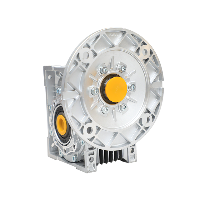
The reliability of this drive technology stems directly from its structural engineering and material composition. The mechanics involve sliding friction—a continuous wiping action—rather than the rolling friction found in planetary gears. Therefore, the internal components must withstand high operational temperatures and continuous wear.
The metallurgical pairing of the internal components is a critical design feature intended to maximize longevity. Manufacturers typically machine the worm shaft from high-alloy steel that has been case-hardened and precision-ground. This hardening process ensures the threads endure massive input speeds from the motor without deforming. Conversely, the mating wheel is almost exclusively cast from softer, non-ferrous metals like bronze or brass.
Specifically, this dissimilar metal pairing is highly intentional. The sliding contact mechanism generates significant friction. Utilizing a hardened steel shaft against a softer bronze wheel manages this friction effectively. In practical terms, the softer bronze acts as a sacrificial component. It wears down slowly over years of operation, absorbing the brunt of the mechanical stress. This protects the more expensive steel worm shaft. During routine overhauls, replacing just the bronze wheel is far more cost-effective than replacing the entire gearset.
The external housing protects these vital internals while playing a massive role in thermal management. Historically, cast iron was the undisputed standard due to its extreme durability and vibration-dampening qualities. Today, modern industrial applications increasingly favor aluminum alloy housings for their lightweight nature and superior heat dissipation.
Because the sliding action between steel and bronze generates substantial heat, standard mineral oils are often insufficient. High-quality synthetic lubrication is absolutely critical. Synthetic gear oils, particularly Polyalkylene glycol variants, maintain their viscosity at higher operating temperatures. They create a resilient microscopic film that minimizes metal-to-metal wear. This simple maintenance detail dramatically extends the overall lifespan of the unit.
The versatility of these right-angle drives makes them ubiquitous across multiple sectors. Their design solves specific mechanical challenges that standard inline gearboxes simply cannot handle.
In bustling fulfillment centers and mining operations, conveyor belts must move heavy loads at strictly controlled speeds. A standard AC motor spins far too fast to drive a conveyor directly. Passing this power through a right-angle drive reduces the speed to a manageable rate while multiplying the torque. The 90-degree configuration allows the motor to sit parallel to the conveyor frame. This keeps forklift aisles clear and optimizes facility layout.
When suspending heavy loads mid-air, safety eclipses all other engineering concerns. If power to the motor is suddenly cut, the load absolutely must not free-fall. High-ratio configurations exhibit a property known as self-locking. Because of the steep angle of the worm threads, the gear wheel cannot force the worm shaft to rotate in reverse. This mechanical characteristic acts as a natural fail-safe in hoists and freight elevators.
Modern agriculture relies heavily on precise climate control. Commercial greenhouses utilize automated systems to open massive roof vents or roll up heavy side curtains. These systems require slow, deliberate, and incredibly powerful movements. The self-locking nature of these gearsets ensures that heavy glass vents remain securely open at the exact desired angle. They fight against strong wind gusts without requiring constant motor power.
The food and beverage sector demands machinery capable of operating in strictly regulated, hygienic environments. Bottling lines and automated packaging machines utilize specialized variants of these drives. Washdown applications often feature housings coated with food-grade epoxy. Their smooth surfaces prevent bacterial buildup and withstand high-pressure chemical cleaning.
Engineers frequently select this specific drive technology for its self-locking capability. To fully grasp this advantage, we must look at the physics of the gear mesh. In a standard parallel gearset, power flows seamlessly in both directions. The motor can drive the load, and the load can drive the motor.
In contrast, a worm gearset with a high reduction ratio features a lead angle so shallow that static friction prevents the wheel from turning the shaft. Simply put, the motor can drive the output, but the output cannot back-drive the motor. Ratios of 30:1 or greater typically exhibit this trait.
For machinery designers, this characteristic is highly economical. In applications like inclined conveyors, the self-locking feature acts as a static holding brake. This often eliminates the need to purchase and wire expensive external braking systems. You drastically simplify the machine electrical design and reduce overall production costs.
However, self-locking is not an absolute guarantee in every scenario. In environments subjected to heavy, continuous vibrations, static friction can momentarily break. This might cause a suspended load to slowly creep downward. Therefore, for strict safety compliance in critical lifting applications, engineers must still incorporate supplementary mechanical brakes for absolute redundancy.
When browsing supplier catalogs for a new drive system, buyers frequently encounter the term NMRV. Rather than a specific brand, this denotes a highly standardized, globally recognized series of right-angle reducers. The NMRV Gearbox has become the industry benchmark for modern light-to-medium duty power transmission.
Historically, power transmission units were bulky, custom-cast behemoths that made replacement a logistical nightmare. The NMRV series revolutionized the market by introducing strict dimensional standardization. You will typically find center distances ranging from 025 up to 150 millimeters. This universal standardization means an NMRV unit from one facility can often serve as a direct drop-in replacement for a broken unit on the line. This minimizes costly machinery downtime and simplifies spare parts procurement.
The widespread adoption of this series is driven by distinct structural advantages. First, sizes 025 through 090 utilize a die-cast aluminum alloy enclosure. This lightweight construction drastically reduces the overall weight of the drive system. It is particularly beneficial when the unit must be mounted directly onto moving machinery components where excess mass hinders performance.
Additionally, aluminum possesses excellent thermal conductivity. The heavily ribbed, square design of an NMRV enclosure maximizes surface area. This allows the intense heat generated by internal sliding friction to dissipate rapidly into the surrounding air. Finally, unlike untreated cast iron, the aluminum alloy naturally resists oxidation. This makes it highly suitable for damp environments or facilities with fluctuating humidity levels. For heavier torque demands, sizes 110 to 150 transition to robust cast iron housings to maintain structural integrity.
The most common objection engineers raise when evaluating right-angle technology is mechanical efficiency. To make an informed purchasing decision, you must understand the physics behind this efficiency loss and how thoughtful system design mitigates it.
In standard inline gearboxes, gear teeth engage through rolling contact. This minimizes friction and allows for efficiencies often exceeding 95 percent. Conversely, a right-angle design operates via sliding contact. This wiping action effectively transmits heavy torque at a 90-degree angle, but it inherently generates heat. This results in energy loss.
The mechanical efficiency of these units is inversely proportional to their reduction ratio. A low-ratio unit like 7.5:1 might achieve a respectable 85 to 90 percent efficiency. However, pushing a single-stage unit to a high ratio like 100:1 might cause operational efficiency to plummet closer to 50 percent.
To assist in the decision-making process, review this direct comparison between right-angle and inline helical alternatives.
| Feature | Worm Gear Reducer | Helical Gearbox |
|---|---|---|
| Friction Type | Sliding friction (generates more heat) | Rolling friction (minimal heat generation) |
| Mechanical Efficiency | 50% to 90% depending on ratio | Consistently high, often 95%+ |
| Space Requirement | Highly compact, 90-degree configuration | Requires more linear space (inline setup) |
| Self-Locking Capability | Yes, at high reduction ratios | No, requires external braking systems |
| Initial Cost | Highly cost-effective and economical | Generally more expensive to manufacture |
If an application requires continuous operation where energy consumption is the absolute highest priority, engineers might opt for a helical unit. However, buyers must carefully weigh the cost-effectiveness, self-locking nature, and compact footprint of the right-angle design against the higher energy efficiency of helical gears.
Selecting the correct mechanical drive is a precise engineering task. Oversizing leads to unnecessary capital expenditure and wasted physical space. Undersizing inevitably results in premature mechanical failure. Follow this practical engineering checklist to ensure accurate sizing for your machinery.
The fundamental purpose of the Industrial Gearbox is to convert high-speed motor rotation into low-speed, high-torque output. First, calculate the precise RPM required for your driven shaft. Divide the motor input RPM by this desired output RPM to find your target reduction ratio. Next, calculate the running torque required to physically move your load. Ensure the selected unit rated output torque comfortably exceeds this nominal requirement.
Examine the physical envelope where the drive system will be installed. If space is abundant, standard cast-iron industrial units are perfectly sufficient. However, if you are designing automated doors or compact conveyor modules, evaluate spatial constraints closely. Specifying a compact aluminum housing allows you to achieve the necessary power transmission without altering the machine external dimensions.
The nominal torque rating of a catalog unit assumes a perfectly smooth load operating for eight hours a day. Real-world applications rarely fit this pristine profile. The Service Factor is a crucial multiplier used to adjust the required torque based on operational severity. A uniform light belt conveyor operating a few hours a day might use a Service Factor of 1.0. In stark contrast, a rock crusher operating 24 hours a day with heavy shock loads requires a higher service factor like 1.75 or 2.0. This ensures the internal bronze gear does not strip under sudden violent stress.
Modern units offer exceptional mounting flexibility. Flange mounting is ideal for direct coupling to the driven machine, ensuring perfect alignment. Foot mounting is the traditional method of securing the housing to a baseplate, useful for chain-driven setups. Alternatively, a shaft-mounted design features a hollow output shaft that slides directly onto the machine drive shaft. Secured by a torque arm, this highly efficient method eliminates the need for external couplings, saving significant space.
Whether you are engineering a sprawling warehouse conveyor matrix or a precise greenhouse ventilation system, understanding right-angle power transmission optimizes your machinery. These units offer an unparalleled combination of high reduction ratios, compact footprints, and inherent safety features.
Their self-locking nature adds vital security to lifting systems. Meanwhile, modern aluminum designs ensure they remain lightweight and resistant to harsh environments. By carefully calculating your load requirements, service factors, and spatial constraints, you can select a drive system that guarantees long-term reliability.
Proper maintenance, particularly the use of high-grade synthetic lubricants, will maximize mechanical efficiency and protect your investment. If you are ready to integrate a robust Worm Gear Motor into your next project, review your specific load requirements. Explore the extensive catalog at Huake Gearbox to find the perfect fit for your operational needs.
Whether a unit can be back-driven depends entirely on the static friction angle and the internal reduction ratio. Low-ratio configurations like 5:1 to 15:1 have steep lead angles and can often be driven in reverse by the load. However, high-ratio units have very shallow lead angles. In these setups, the friction between the gears is greater than the rotational force. This creates a self-locking state where the load cannot drive the shaft in reverse.
The lifespan depends heavily on application severity and maintenance practices. Under normal operating conditions with a properly calculated Service Factor, a high-quality unit can last between 10,000 to 20,000 operational hours. Because the internal bronze gear is designed to wear down gradually, routine oil changes are critical. Removing contaminated oil prevents suspended bronze particulates from acting as an abrasive compound, thereby extending operational life significantly.
The primary difference lies in geometry and friction mechanics. The right-angle design utilizes sliding friction. This makes it highly compact, cost-effective, and capable of self-locking, though it sacrifices some mechanical efficiency. A planetary gearbox features an inline design utilizing rolling friction among multiple internal gears. Planetary units achieve exceptionally high torque density and efficiencies above 95 percent, but they lack self-locking capabilities and are more complex to manufacture.
This specific metallurgical pairing manages the high sliding friction inherent in the design. The input shaft is machined from hardened steel, while the mating wheel is cast from a softer bronze alloy. The dissimilar metals prevent galling or metal welding under extreme pressure. Furthermore, this design is intentionally sacrificial. The less expensive bronze takes the majority of the wear over time, protecting the complex steel shaft and making future rebuilds far more cost-effective.
Calculating the ratio is straightforward. You simply count the number of teeth on the bronze worm wheel and divide it by the number of threads on the steel worm shaft. For example, if the wheel has 60 teeth and the shaft has a single thread, the reduction ratio is 60:1. This means the motor must turn 60 times to complete one full revolution of the output shaft.
Generally, these gearboxes are not recommended for continuous high-speed output applications. The sliding friction generates excessive heat at high speeds, which rapidly degrades the lubricating oil and accelerates bronze gear wear. They excel in applications requiring significant speed reduction and high torque multiplication. If your application demands high-speed continuous output, an inline helical or planetary gearbox is a much better engineering choice.


