
- All
- Product Name
- Product Keyword
- Product Model
- Product Summary
- Product Description
- Multi Field Search


Views: 0 Author: Site Editor Publish Time: 2026-10-16 Origin: Site


Gearboxes act as the beating heart of modern mechanical power transmission. Picking the wrong unit causes mechanical failure. Worse, it leads to expensive, unplanned downtime. This severely impacts a facility's bottom line. In this comprehensive guide, you will learn about the primary categories of these vital components. We will help you make a highly informed, data-driven industrial purchasing decision.
At its core, an Industrial Gearbox is a highly engineered, enclosed system of gears. It alters torque and speed between a driving device—such as an electric motor or diesel engine—and a driven load. By manipulating the rotational speed, these mechanical devices ensure heavy machinery operates at the optimal mechanical advantage. They effectively convert high-speed, low-torque motor outputs into the low-speed, high-torque power required by heavy equipment.
In heavy-duty sectors like manufacturing, mining, and cement production, the gear unit is not just a peripheral accessory. It is the foundational component. It dictates the operational efficiency, safety, and lifespan of the entire machinery setup. A properly specified system reduces energy consumption and minimizes mechanical wear on the motor. Furthermore, it prevents catastrophic operational failures.
Conversely, an improperly sized unit inevitably leads to excessive heat generation and rapid gear wear. This results in an unacceptably high total cost of ownership due to frequent maintenance.
Looking at recent developments in global manufacturing, the demand for power transmission systems is shifting rapidly. Modern facilities no longer just want raw power. They demand high energy efficiency, compact designs, and seamless integration with predictive maintenance sensors. Industry data shows a massive push toward automated smart factories. This trend forces engineers to select gear units that deliver precise motion control while minimizing energy loss. Evaluating your operational demands against the primary architectures is the critical first step in keeping up with these modern efficiency standards.
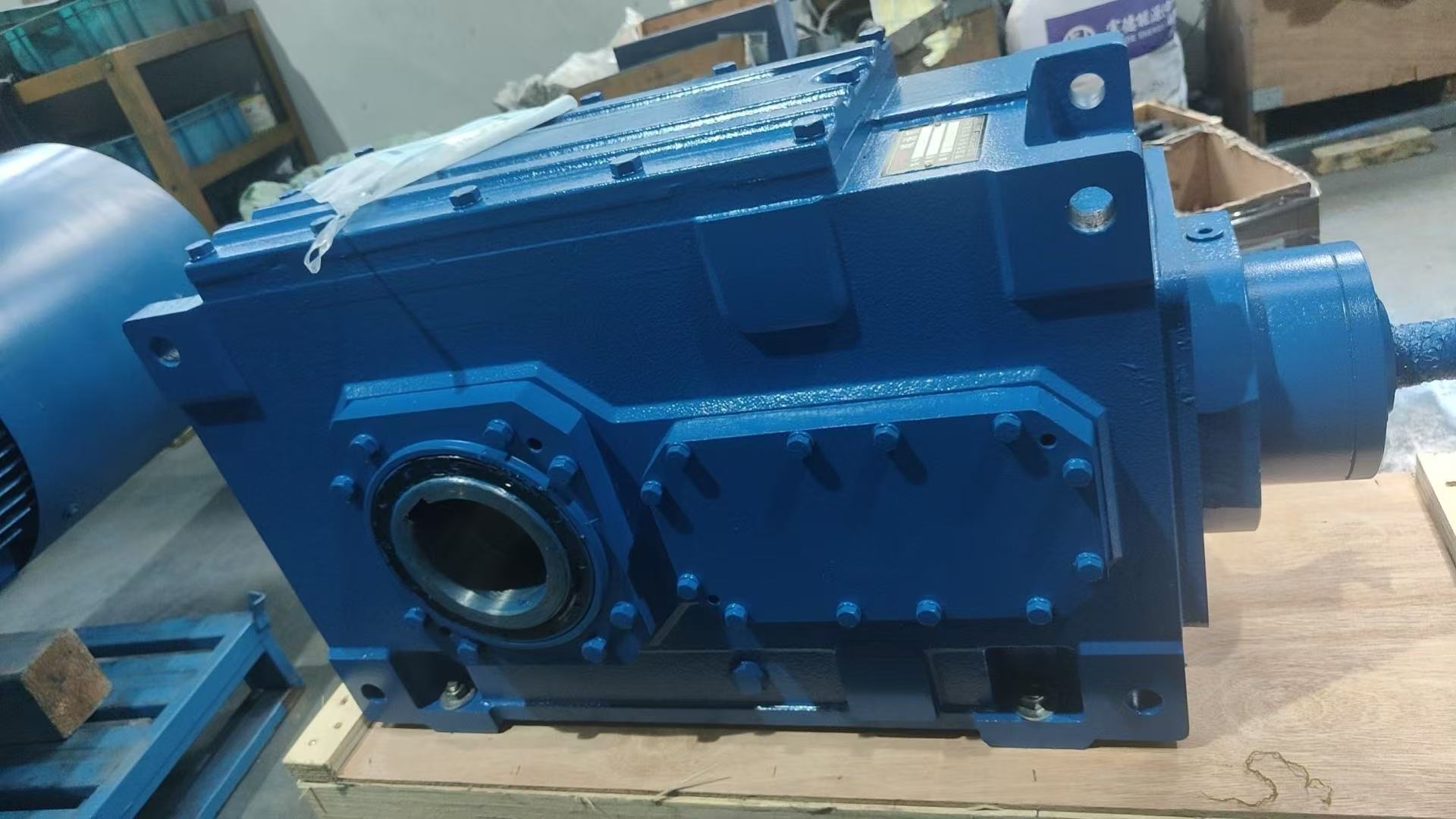
The Helical Gearbox stands out as the workhorse of modern industry. The teeth on these gears are cut at an angle to the face of the gear. This specific geometry allows the teeth to engage gradually. What is the result? You get smoother, significantly quieter operation compared to traditional spur gears, even at exceptionally high speeds.
From an engineering perspective, these units deliver exceptional efficiency, often exceeding ninety-five percent. For instance, industrial-grade equipment like the robust HB Series features rigid cast iron housings and versatile parallel or right-angle shaft designs. They handle immense torque loads with ease. This makes them the default choice for heavy conveyors, crushers, and large-scale industrial mixers. If your facility runs continuous, heavy-duty cycles, this architecture offers the best long-term mechanical reliability.
Space constraints often dictate machinery layout on the factory floor. When power must turn a corner, a Bevel Gearbox is the exact solution required. These units utilize cone-shaped gears to transmit motion between intersecting shafts. Most commonly, they operate at a strict right angle.
Engineers typically specify spiral bevel gears for industrial applications. The curved teeth provide a higher contact ratio. This design significantly increases load-carrying capacity and reduces operational vibration. You will frequently find these systems deployed in mining equipment, large cooling towers, and automated packaging machinery. They excel in scenarios requiring directional changes without sacrificing mechanical efficiency.
How do you extract massive power out of a tiny footprint? You utilize a Planetary Gearbox. The structural design mimics our solar system. A central sun gear drives multiple planet gears, which rotate seamlessly within an outer ring gear.
Distributing the load across multiple gear teeth simultaneously is a mechanical game-changer. It creates an incredibly high torque density. Automation robotics, wind turbines, and precision solar tracking systems rely heavily on this specific design. The compact nature reduces the overall weight of the machinery. However, the complex internal structure does require precise manufacturing tolerances and careful lubrication management to prevent overheating during continuous operation.
Sometimes, speed reduction and operator safety take precedence over pure mechanical efficiency. A Worm Gearbox pairs a screw-like worm shaft with a mating worm wheel. This unique setup achieves massive speed reductions in a single mechanical stage.
The most distinct engineering advantage here is the inherent self-locking characteristic. The worm can easily turn the gear, but the gear cannot turn the worm. This acts as a natural brake to prevent back-driving. It is an invaluable safety feature for lifting equipment, heavy hoists, and elevators. While they are slightly less energy-efficient due to sliding friction, their near-silent operation and compact right-angle design make them indispensable for specific lifting and positioning tasks.
To help visualize the engineering differences, review this core comparison of the four primary architectures:
| Gearbox Type | Efficiency | Torque Capacity | Key Engineering Advantage | Typical Application |
|---|---|---|---|---|
| Helical | Very High | High | Smooth operation, high durability | Conveyors, crushers, extruders |
| Bevel | High | Medium to High | 90-degree power transmission | Cooling towers, mining machinery |
| Planetary | High | Very High | Compact size, maximum torque density | Robotics, wind turbines, servo motors |
| Worm | Moderate | Low to Medium | Self-locking safety, quiet running | Hoists, elevators, packaging machines |
Do not rely on guesswork when sizing industrial equipment. An undersized unit will fail prematurely, while an oversized one wastes capital and electrical energy. Follow these concrete engineering parameters for a flawless selection:
First, calculate the exact torque requirement. Look at your motor's running torque and apply an appropriate service factor based on anticipated shock loads. Heavy startup loads require a higher safety margin.
Second, evaluate the thermal rating. Heavy continuous operations generate significant heat. Ensure the housing design—like ribbed cast iron—can dissipate this thermal energy effectively without degrading the lubricating oil.
Third, consider the mounting space. If you have a narrow physical envelope, right-angle bevel or compact planetary designs will serve you far better than bulky parallel helical setups.
Finally, assess the operating environment. High dust levels, moisture, and extreme temperature fluctuations dictate the specific type of sealing and synthetic lubrication required to prevent premature bearing failure.
To determine the exact ratio, divide the input speed of your motor by the desired output speed of your driven equipment. For example, a motor running at fifteen hundred RPM driving a conveyor that needs one hundred and fifty RPM requires a ten-to-one ratio. Always factor in potential load fluctuations to ensure stable, continuous operation.
Overheating typically stems from three primary engineering issues. These include improper lubrication levels, excessive load beyond the rated capacity, or severe mechanical misalignment between the motor and the driven shaft. Regular monitoring of oil viscosity and routine vibration analysis can identify these issues long before catastrophic failure occurs.
Selecting the perfect mechanical drive is a complex engineering challenge, but you do not have to navigate it alone. Upgrading your facility with high-performance units directly reduces maintenance downtime and boosts overall profitability. Evaluate your specific torque, speed, and spatial requirements carefully. Ready to build a more reliable production line? Explore the robust, high-efficiency solutions tailored for heavy industry at Huake Gearbox to find the exact match for your operational needs.


