
- All
- Product Name
- Product Keyword
- Product Model
- Product Summary
- Product Description
- Multi Field Search


Views: 0 Author: Site Editor Publish Time: 2026-10-13 Origin: Site


In the complex world of manufacturing and facility engineering, utilizing precise terminology dictates system efficiency. Procurement specialists and mechanical designers frequently mix up these terms, treating them as interchangeable components. While they operate in tandem within a broader industrial drive architecture, they are fundamentally different pieces of equipment.
Making an incorrect choice during the design phase leads to bloated maintenance budgets and wasted physical space on the factory floor. The core issue stems from a misunderstanding of power generation versus power modification. A gear motor is an integrated electromechanical unit containing both the motor and the gearing mechanism. In contrast, a standalone unit is strictly a passive mechanical component used solely for speed reduction. This analysis provides an objective engineering perspective, equipping buyers with the technical knowledge required to select the optimal configuration for specific field applications.
To truly understand the distinctions in this equipment, we must first isolate the individual components. From an engineering standpoint, this is a passive device. It does not generate mechanical power on its own. Instead, it must be driven by an external power source, typically an AC or DC electric motor, an internal combustion engine, or a hydraulic system.
The primary function is mechanical power transmission. It takes the high-speed, low-torque input generated by the prime mover and converts it into a low-speed, high-torque output. This torque multiplication happens through specific internal gear arrangements. Whether utilizing helical, bevel, worm, or planetary gear sets, the mechanism allows a standard motor to move exceptionally heavy loads that it would otherwise lack the brute force to manage.
In industrial procurement nomenclature, this component is frequently referred to as a speed reducer. The internal architecture consists of precision-machined gears, robust input and output shafts, rolling-element bearings to support radial loads, and heavy-duty seals to retain lubricating oil. Because it is a standalone unit, it features a standardized input flange designed to accept a separate motor via a mechanical coupling.
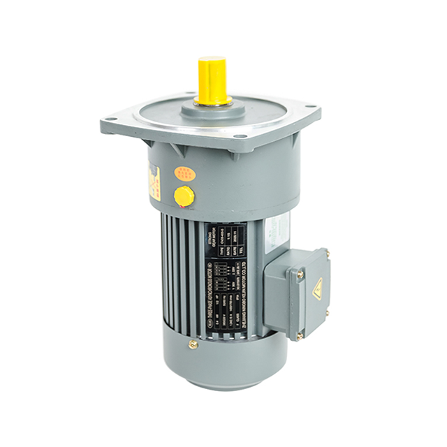
This system represents a highly integrated approach to mechanical power transmission. By definition, it is a single, cohesive component housing both an electric motor and a gear train within a unified framework. Instead of treating power generation and power modification as two separate entities requiring field assembly, manufacturers engineer them as a single continuous system.
The operational principle relies heavily on direct internal integration. The electric motor portion generates the initial high-speed rotation. However, instead of outputting this raw speed through a standard motor shaft to an external coupling, the rotor shaft extends directly into the gear train. The attached gears immediately modify that rotational power. Across global manufacturing sectors, this seamless unit is widely known as a geared motor.
The primary appeal of this design is guaranteed synergy. When engineers specify an integrated unit, they invest in a system where the motor's torque curve, thermal capacity, and operational speed are perfectly matched to the reducer's mechanical limits. For instance, modern R-series helical units can handle output torques up to 18,000 Nm with ratios spanning from 1.3 to over 28,000. This factory-level matching ensures optimal energy efficiency and provides a streamlined solution right out of the box.
Looking at current industrial drive trends, there is a massive shift toward IoT-enabled, high-efficiency integrated systems. Driven by stringent global energy standards, plant managers are migrating from older modular setups to IE3 or IE4 class drive packages. Factory floor real estate is becoming increasingly expensive, pushing engineers to prioritize compact footprints.
Furthermore, original equipment manufacturers are actively moving away from labor-intensive setups. The industry recognizes that the hidden costs of standalone systems—specifically the labor hours required for laser alignment and the downtime caused by coupling shear—often outweigh the benefits of modularity. Consequently, the market is pivoting toward factory-sealed, energy-optimized units that support real-time condition monitoring. Tracking vibration signatures and oil degradation directly from the drive unit is rapidly becoming the new standard in automated production lines.
When evaluating this dynamic, the distinctions become vividly clear upon analyzing power generation, physical footprint, alignment requirements, and maintenance protocols. The table below outlines the empirical differences between the two systems.
| Feature Criteria | Standalone Speed Reducer | Integrated System |
|---|---|---|
| Power Generation | Passive mechanical device. Cannot generate motion independently. | Active electromechanical device. Generates and reduces power simultaneously. |
| Physical Footprint | Larger overall footprint. Requires external couplings and extended baseplates. | Highly compact. Eliminates external couplings and adapter plates. |
| Shaft Alignment | Requires manual alignment by technicians using dial indicators or laser tools. | Pre-aligned at the factory. The motor pinion interfaces directly with the gear train. |
| Component Replacement | Modular. A failed motor can be swapped while leaving the mechanical drive in place. | Integrated. Catastrophic motor failure may require replacing the entire unit. |
The greatest strength of a standalone setup is its unparalleled modularity. By keeping the mechanical and electrical components separate, facility engineers have the freedom to pair the reducer with highly specialized prime movers. If an application is located in a hazardous chemical plant, a standard gearbox can be coupled with a specialized explosion-proof motor.
In practical terms, standalone systems often result in cheaper targeted replacements. Picture a scenario where a sudden electrical voltage spike burns out the stator windings. Instead of scrapping the entire drive assembly, maintenance teams simply unbolt the damaged motor, purchase a replacement off the shelf, and attach it to the existing gearhead.
This modularity inevitably comes with distinct mechanical drawbacks. The combination of a motor, a coupling mechanism, and a reducer requires a significantly larger physical footprint. This bulky arrangement proves highly problematic in space-constrained manufacturing facilities.
More importantly, there is a severe risk of shaft misalignment. Picture a maintenance technician spending hours painstakingly adjusting shim packs under a motor baseplate. If the shafts are misaligned by even a fraction of a millimeter, it induces parasitic radial loads. Over time, this friction leads to excessive vibration, premature wear on bearings, and eventual catastrophic failure.
The most significant benefit here is the compact, space-saving design. Because the motor and gearhead share a common housing, it is the ideal solution for tight machine envelopes. Buyers also benefit from guaranteed compatibility. Manufacturers conduct rigorous load testing to ensure the motor will not overpower the gears, maximizing overall longevity.
Specifically, field installation is vastly simplified. Because there is no external coupling, shaft alignment is entirely eliminated. Technicians simply bolt the unit to the machine frame, wire the electrical connections, and begin operation. This plug-and-play nature drastically reduces installation time and eliminates user-end assembly errors.
The primary drawback is a noticeable reduction in long-term flexibility. Once purchased, the specifications are largely locked in. If the demands of the application change—requiring a motor with a different voltage or a specific IP enclosure rating—it is often impossible to swap out just the motor.
In addition, repairing highly sealed or proprietary designs can be complex. If a gear tooth breaks or the electrical stator fails, the entire assembly must often be removed from the production line and sent to a specialized facility for remanufacturing. This lack of modularity can increase operational downtime if spare units are not kept in inventory.
Making the correct engineering decision requires a thorough assessment of your specific operational constraints. When finalizing your procurement strategy, evaluate the following criteria directly against your field conditions.
Assess Your Space Constraints: Physical space is often the most rigid constraint in facility design. If the machinery requires a drive mechanism to fit within a tight envelope—such as inside the frame of a compact conveyor system or an automated guided vehicle—engineers should lean heavily toward an integrated unit. Eliminating external coupling hardware makes it the logical choice.
Evaluate Your Motor Requirements: Consider the environmental and electrical demands of your operation. Do you require a highly specific motor brand to maintain inventory consistency? Does the environment necessitate a washdown-duty, stainless steel motor for food processing? In scenarios demanding specialized power generation, utilizing a standalone unit with a standard NEMA or IEC input flange provides necessary flexibility.
Consider Total Cost of Ownership: Upfront purchasing cost is only one metric. Engineers must factor in installation time and labor rates. Integrated units save significant money upfront on labor, laser alignment services, and coupling hardware. Conversely, standalone units might offer a lower lifecycle cost in harsh environments where motors frequently burn out, as replacing an isolated motor is cheaper.
Analyze Maintenance Capabilities: Be realistic about the technical expertise of your on-site maintenance staff. Does your team have the specialized tools and training required to perfectly align a motor and a speed reducer? If alignment expertise is lacking, opting for a factory-aligned integrated unit is a proactive way to prevent user error.
Theoretical differences translate into distinct practical applications across various industrial sectors. Understanding where each system excels helps narrow down the selection process.
Where Integrated Systems Excel: Because of their reliable and compact nature, these units are the backbone of light-to-medium manufacturing. They excel in applications requiring consistent speed and torque in confined spaces. You will primarily find them driving airport baggage handling systems, bottling lines, pharmaceutical packaging machinery, and automated warehouse conveyors.
Where Standalone Systems Excel: Modular units dominate heavy industry where raw power, extreme durability, and rapid component replacement are prioritized. They are the standard choice for heavy-duty mining conveyors, large-scale chemical agitators, cement kilns, and extrusion machinery. In these extreme environments, isolating the mechanical gear train from the electrical motor acts as a vital operational safeguard.
A standalone reducer is merely a passive mechanical component requiring an external power source to function. In contrast, an integrated system combines both power generation and mechanical reduction into one cohesive unit, creating a highly efficient and compact drive package.
Your final choice depends entirely on your specific field needs. Evaluate your physical space, upfront budget, and in-house maintenance capabilities carefully before making a procurement decision. Selecting the right equipment optimizes daily operations, prevents parasitic mechanical losses, and ensures long-term reliability.
Whether you need a standalone modular setup or a fully integrated solution, finding the right equipment is crucial for your bottom line. Explore a comprehensive range of high-performance gear motors and engineered drives at Huake to find the perfect fit for your next industrial project.
Yes, in standard industrial engineering terminology, a speed reducer and a gearbox refer to the exact same equipment. Both terms describe an enclosed mechanical unit containing gear sets designed to reduce the high rotational speed of an incoming motor shaft in order to exponentially increase the output torque.
Technically, you can attach an electric motor to a standalone unit using a C-face adapter, external couplings, and a fabricated mounting base. This creates a functional motorized drive. However, industry professionals do not classify this as a true integrated system, as it lacks the seamless, coupling-free internal architecture of a factory-built unit.
Empirical data demonstrates that a factory-integrated system is generally more energy-efficient. Because the manufacturer meticulously optimizes the gear-to-motor ratio and directly connects the rotor to the gear train, it eliminates the minor mechanical energy losses that naturally occur when utilizing external couplings and managing slight shaft misalignments.
The repair protocol depends heavily on the specific manufacturer's design architecture. On some modular integrated designs, maintenance teams can unbolt and replace the motor stator and rotor assembly. However, on highly compact or hermetically sealed units, a motor failure typically means the entire unit cannot be easily repaired in the field and must be replaced entirely.
Sizing requires calculating the application's required output torque, target output speed, and the service factor based on operating hours and shock loads. Engineers typically divide the prime mover's input speed by the target output speed to determine the necessary exact gear ratio, then verify that the selected unit's mechanical and thermal ratings exceed the application's maximum demands.
It depends entirely on the internal gear type. Helical, bevel, and planetary units are generally back-drivable, meaning applying torque to the output shaft will turn the motor. However, high-ratio worm gear units are often self-locking. In these specific designs, friction prevents the output shaft from driving the input shaft backwards, which serves as a natural holding brake in hoisting or inclined conveyor applications.


