
- All
- Product Name
- Product Keyword
- Product Model
- Product Summary
- Product Description
- Multi Field Search


Views: 0 Author: Site Editor Publish Time: 2026-10-19 Origin: Site


Gears typically conjure images of interlocking toothed wheels spinning in unison. Heavy industrial setups demand highly compact power. Finding the right transmission system to fit within constrained physical footprints is notoriously difficult. Often found buried deep within the chassis of heavy machinery, this specific drive mechanism acts as a powerhouse of modern engineering. It delivers high-torque output exactly where space is at an absolute premium.
In this comprehensive guide, we explore the fascinating mechanics behind these systems. You will learn about their unique physical properties, how to select optimal units for your factory floor, and the specialized maintenance required to keep them running efficiently.
Understanding industrial terminology often requires looking closely at the physical characteristics of the components themselves. The naming convention of this specific gear system is entirely visual and historical, rather than based on a complex mathematical formula.
A standard setup consists of two primary components. The first is the driving input shaft, a cylinder featuring a continuous, helical spiral thread. Engineers technically call this component the worm. When you observe it in motion, the rotational movement of this spiral thread mimics the undulating, forward-crawling motion of an earthworm pushing through soil.
The second component is the driven gear. This part looks much like a traditional spur gear but features slightly angled and curved teeth designed to perfectly cradle the spiral threads of the driving shaft. Consequently, the entire assembly is known as a Worm Gear mechanism simply because the driving component looks and acts like a mechanical worm pulling the wheel forward.
The mechanical principle behind this design is ancient. It traces its roots back to the Archimedes screw, a device invented in ancient Greece to pump water against gravity using a continuous spiral surface inside a hollow pipe. Over centuries of trial and error, engineers realized that by mating a modified screw mechanism with a toothed wheel, they could transmit incredibly heavy rotational force. During the Industrial Revolution, this concept was refined using hardened metals. It eventually evolved into the robust industrial transmission systems we rely on today.
The operational physics here differ significantly from standard parallel-axis setups. Instead of relying on simple interlocking teeth, this design utilizes specific geometric alignments and friction dynamics. This allows for efficient power transfer under heavy loads.
The most defining characteristic of this mechanism is its ability to redirect mechanical power. The input shaft and the output shaft are positioned at a 90-degree angle to one another on non-intersecting planes. This unique configuration creates a highly efficient Right Angle Transmission system. In cramped industrial environments where floor space is limited, the ability to turn rotational force by 90 degrees allows facility managers to mount motors parallel to conveyor belts or machinery. This simple adjustment saves significant lateral space.
In traditional helical or spur gears, the teeth roll against each other. This creates a highly efficient rolling friction. In contrast, the threads of a worm shaft actually slide across the teeth of the gear. This sliding action is fundamental to how torque is transferred. While it allows for incredibly smooth engagement, sliding friction generates a substantial amount of heat and mechanical resistance. Consequently, the efficiency of these systems is generally lower than that of rolling gears. Plant operators must carefully consider thermal management during continuous operation.
One of the most critical engineering advantages of this mechanism is the self-locking effect. In setups with a high reduction ratio, typically 30:1 or greater, the lead angle of the worm thread is very shallow. Because the static friction exceeds the back-driving force, the gear simply cannot turn the worm shaft. If power to the motor is suddenly cut, the load stops immediately and remains permanently locked in place. This inherent irreversibility is a vital safety feature in hoisting, lifting, and elevator applications. It prevents heavy loads from free-falling without relying entirely on external braking systems.
To function reliably in harsh, dust-filled industrial environments, the bare gears must be precisely aligned and protected within an enclosed mechanical unit.
The input shaft endures immense rotational stress and continuous sliding friction. To withstand this punishing environment, it is almost exclusively manufactured from high-carbon, hardened steel. The surface of the threads is often precision-ground and polished to a mirror finish. This critical manufacturing step minimizes abrasive wear against the mating gear.
Because of the continuous sliding friction, using steel for both components would result in galling. Galling is a severe form of wear where the metals literally weld together under heat and tear apart. To prevent this catastrophic failure, the output gear is typically machined from a softer, ductile yellow metal. Phosphor bronze or brass is the industry standard. In this dissimilar metal pairing, the bronze acts as a sacrificial element. It slowly wears down over thousands of hours of operation, protecting the much more expensive and difficult-to-replace steel input shaft.
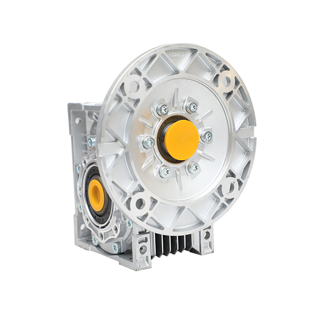
The gears are enclosed in a rigid casing that maintains exact shaft alignment and contains the vital lubricating oil bath. Heavy-duty tapered roller bearings support the shafts, absorbing both radial and thrust loads. When these carefully machined components are assembled into a single enclosed unit, it becomes a complete Worm Gear Reducer. It arrives ready to be bolted directly onto industrial machinery. The housing also features cooling fins to aggressively dissipate the heat generated by the internal sliding friction.
Despite their lower mechanical efficiency compared to some modern alternatives, these systems remain a staple in engineering. They offer several unique performance benefits that cannot be easily replicated by other gear types.
Standard gear types require multiple gear pairs to achieve high reduction ratios. This inevitably results in large, bulky gearboxes. However, a single worm and wheel pairing can easily achieve reduction ratios ranging from 5:1 up to 100:1 in a single stage. This allows engineers to drastically reduce motor speed and multiply torque within a remarkably compact footprint.
Industrial machinery often experiences sudden spikes in load, known as shock loads. Imagine a rock crusher temporarily jamming or a heavy conveyor belt starting up under full capacity. Because the output gear is made of a ductile metal like bronze, it possesses a certain degree of elasticity. This allows the gear teeth to absorb and dissipate sudden mechanical shocks without fracturing. Brittle, hardened steel gears might shatter under similar circumstances.
The sliding engagement between the helical threads and the gear teeth ensures continuous, smooth contact. There is no sudden impact of teeth engaging and disengaging. This sudden impact is the primary source of the clanking noise in spur gears. As a result, these reducers operate with exceptionally low noise and vibration levels. They are ideal for environments where noise pollution must be strictly minimized, such as theater stage automation, libraries, or hospital equipment.
The basic mechanism has been adapted over decades into various configurations. These designs suit different industrial requirements, ranging from light-duty packaging lines to heavy-duty mining operations.
The physical geometry of the gear mesh determines its load capacity. Non-Enveloping is the simplest design, where the worm is a straight cylinder. Contact between the threads and the gear teeth occurs at a single microscopic point, which limits its overall torque capacity.
In contrast, a Single Enveloping design features gear teeth that are curved to wrap partially around the straight worm shaft. This increases the contact area from a point to a line, significantly improving load capacity. This is the most common industrial configuration today. Finally, Double Enveloping involves both the gear teeth and the worm shaft being curved to wrap around each other in an hourglass shape. This maximizes contact area, allowing for extreme torque transmission in a smaller unit. However, it is highly complex and expensive to manufacture.
In the modern market, standardization is crucial for rapid maintenance and replacement. The NMRV Gearbox represents the global industry standard for lightweight, highly adaptable reducers. This specific design is characterized by a die-cast aluminum alloy housing. For instance, modern standardized units offer frame sizes ranging from 025 to 150. These units can seamlessly handle input power from a mere 0.06kW up to a robust 15kW, delivering output torque reaching 3000Nm.
This aluminum construction provides excellent heat dissipation and natural corrosion resistance without the need for heavy, prone-to-chipping paint coatings. Furthermore, these units are designed with extreme modularity in mind. They utilize standard IEC motor flanges and hollow output shafts. Factory technicians can easily swap motors, alter mounting positions, or integrate them into existing automated systems with minimal engineering modifications.
Selecting the correct transmission system requires an objective evaluation of operational priorities. Engineers frequently weigh the compact benefits of worm mechanisms against the high-efficiency performance of helical gearboxes. To make this actionable, you must evaluate your specific factory floor constraints.
The primary drawback of sliding friction is energy loss. A high-ratio reducer might only operate at 60 to 80 percent efficiency. This means a significant portion of the electric motor power is lost as thermal energy. Helical gears, which utilize rolling friction, consistently operate at 95 to 98 percent efficiency. If energy consumption and continuous thermal management are your absolute primary concerns for a 24/7 operation, helical gears are statistically superior.
However, when installation space is severely restricted, the worm mechanism is unmatched. Helical gearboxes that attempt to provide a 90-degree turn usually require the addition of bevel gears. These setups are bulky, heavy, and expensive. The compact nature of right-angle transmission provided by the worm mechanism makes it the default, undisputed choice for tight mechanical envelopes.
| Feature | Worm Gear Reducer | Helical Gearbox |
|---|---|---|
| Friction Type | Sliding | Rolling |
| Efficiency | 50% - 85% (Lower) | 95% - 98% (Higher) |
| Initial Cost | Highly Cost-Effective | Generally Higher |
| Configuration | Naturally Right Angle | Parallel or Right Angle |
| Self-Locking | Yes (at high ratios) | No |
| Noise Level | Very Low | Moderate |
Maintaining these systems requires a fundamentally different approach compared to standard helical or spur gears. The unique geometry that allows for compact speed reduction also introduces specific mechanical challenges. Understanding tribology, the science of interacting surfaces in relative motion, is critical for extending the operational lifespan of any gear assembly.
The defining mechanical characteristic here is sliding friction. This constant sliding action creates significant hydrodynamic pressure and generates substantial thermal energy. If this heat is not properly managed, the structural integrity of the softer bronze wheel can degrade rapidly. Thermal expansion can alter the precise meshing tolerances between the gears. This leads to accelerated wear patterns such as scoring, pitting, or even catastrophic galling. To overcome these challenges, industrial operators must implement strict thermal management protocols. Monitor the operational temperature of the gearbox housing and ensure that the equipment never exceeds its engineered load capacities.
Because of the high sliding friction and the dissimilar metals used in the assembly, selecting the appropriate lubricant is the single most important maintenance decision. Standard extreme pressure gear oils, which are highly effective for steel-on-steel helical gears, are often detrimental here. Many conventional extreme pressure additives contain active sulfur or phosphorus compounds. Under high heat, these active chemicals react with the copper present in the Worm Wheel. This causes severe chemical corrosion and rapid material loss.
Instead, operators must utilize lubricants specifically formulated for these systems. Modern engineering standards typically recommend compounded mineral oils containing friction modifiers such as tallow or advanced synthetic Polyalkylene Glycol oils. Synthetic oils are highly recommended for heavy-duty applications. They inherently reduce sliding friction, lower operating temperatures, and do not chemically react with yellow metals.
Looking at the broader industrial landscape, the demand for highly compact power transmission is rapidly evolving. Recent market analyses highlight a significant shift toward smart manufacturing and predictive maintenance. Because sliding friction generates detectable heat signatures, modern facilities are increasingly integrating Internet of Things thermal sensors directly onto gearbox housings. These sensors monitor temperature spikes in real-time. They alert technicians to lubrication breakdowns long before the bronze gears suffer irreversible damage.
Furthermore, the push for energy efficiency is driving innovations in lubricant technology. The transition from traditional mineral oils to advanced synthetic Polyalkylene Glycol lubricants is becoming an industry standard. This transition allows facilities to claw back some of the efficiency lost to sliding friction while significantly extending maintenance intervals. As automation continues to shrink the physical footprint of assembly lines, the reliance on lightweight, modular right-angle solutions remains stronger than ever.
The unique mechanical properties of this drive make it an indispensable component across a wide spectrum of industrial sectors. Its ability to provide massive speed reduction, transmit power at a 90-degree angle, and prevent back-driving solves complex engineering problems daily.
In automated manufacturing and distribution centers, conveyor systems require precise speed regulation. The modular aluminum gearbox is frequently utilized here. Its standardized mounting flanges allow for rapid installation along extensive conveyor lines. Furthermore, the inherent shock load tolerance of the bronze wheel absorbs the sudden kinetic impacts that occur when heavy materials drop onto the belt. This action protects the primary drive motor from sudden failure.
Safety is the paramount concern in any application involving vertical lifting. In elevators and hoists, the self-locking phenomenon is heavily leveraged. When the lead angle of the thread is smaller than the coefficient of static friction, the system cannot be driven backward by the load. If power is suddenly cut, the gear mesh acts as an immediate, built-in mechanical brake. This prevents the hoisted load from free-falling.
Industrial packaging equipment must often operate within highly confined spatial footprints. Achieving a 100:1 speed reduction using standard spur gears would require multiple stages, resulting in a bulky drivetrain. By utilizing a compact right-angle transmission, engineers can mount the drive motor perpendicular to the driven shaft. This drastically reduces the overall length of the machinery and maximizes factory floor space.
This specific gear assembly has earned its formidable industrial reputation through unparalleled compact speed reduction and built-in safety features. While the inherent sliding friction requires specialized lubrication and results in slightly lower energy efficiency than helical gears, the benefits are clear. Their cost-effectiveness, shock load tolerance, and self-locking capabilities make them utterly irreplaceable in modern engineering.
Whether you are designing a space-constrained packaging line or a heavy-duty material hoist, choosing the right equipment dictates the success of your operation. Evaluate your load requirements, prioritize thermal management, and select a transmission system that aligns perfectly with your mechanical needs. For high-quality, standardized transmission solutions customized to your factory floor, explore the robust product lineups available at Huake Gearbox to ensure maximum operational uptime.
In engineering terminology, the gear often refers to the entire mechanical assembly. However, when breaking down the specific components, the worm is the hardened, screw-like input shaft that connects to the motor. The wheel is the toothed, circular output gear, typically made of softer bronze, that is driven by the rotation of the input shaft.
This depends entirely on the gear reduction ratio and the lead angle of the threads. In high-ratio setups, such as 50:1 and above, the mechanism is usually self-locking. This means the output load cannot drive the system backward. However, in low-ratio configurations like 10:1, the friction angle can be overcome, and the system can sometimes be back-driven. It should never be solely relied upon as a fail-safe brake without secondary safety systems.
The sliding friction inherent in this mechanism generates extreme heat and wear. By utilizing dissimilar metals, engineers dictate exactly where the wear occurs. It is significantly more cost-effective and mechanically practical for the easily accessible bronze wheel to act as a sacrificial component. It wears down slowly over time, rather than requiring the replacement of the complex, expensive steel input shaft.
NMRV is an internationally recognized industry designation for a specific class of aluminum-housed drive. It represents a highly modular, lightweight, and standardized right-angle gearbox. The standardized flange and shaft dimensions allow engineers and maintenance teams globally to easily swap, upgrade, or replace units across different manufacturing platforms without needing custom-machined mounting brackets.
The lifespan depends heavily on lubrication and load management. Under proper operating conditions with the correct synthetic oil and routine maintenance, a high-quality unit can easily last 3 to 5 years in continuous industrial applications. However, if subjected to extreme shock loads or improper extreme pressure lubricants, the bronze wheel can degrade in a matter of months.
The inefficiency stems directly from the sliding friction between the steel threads and the bronze teeth. Unlike rolling friction found in helical gears, sliding friction creates significant mechanical resistance and heat. This thermal energy represents lost mechanical power, meaning a larger motor might be required to achieve the same output torque compared to a highly efficient rolling gear setup.


