
- All
- Product Name
- Product Keyword
- Product Model
- Product Summary
- Product Description
- Multi Field Search


Views: 0 Author: Site Editor Publish Time: 2026-10-18 Origin: Site


Factory floor space is expensive. You need massive torque to drive heavy machinery, but an inline drive simply will not fit. A worm gear reducer gearbox solves this exact engineering dilemma. It steps down motor speed efficiently while simultaneously amplifying rotational force. In this comprehensive technical guide, you will discover precisely how this mechanism works, its core internal components, and practical selection criteria to ensure maximum longevity in demanding industrial environments.
Key Takeaways:
At its core, this equipment is a highly specialized mechanical device engineered to transfer rotational power between non-intersecting perpendicular shafts. The mechanism consists of two primary components. The first is the worm. This component resembles a threaded screw and couples directly to the input power source, typically an electric motor. The second component is the worm wheel. While it looks similar to a standard spur gear, it features curved teeth specifically designed to mesh perfectly with the threads of the input shaft.
Fundamentally, this device operates as a highly efficient Speed Reducer. When the high-speed motor turns the input shaft, the screw-like threads push against the teeth of the wheel. Because of the engineered gear ratio, it takes multiple rotations of the input screw to turn the wheel just one full revolution. This continuous sliding action takes high-speed low-torque input and converts it into low-speed high-power output.
One of the most defining characteristics of this equipment is its physical geometry. Because the input and output shafts are positioned perpendicular to one another, this unit acts as a space-saving right-angle drive. This layout provides a massive spatial advantage in modern mechanical engineering. In automated manufacturing lines where every inch matters, an inline setup consumes considerable linear space. A 90-degree design allows the driving motor to tuck neatly alongside machinery. You save vital footprint without sacrificing power transmission capabilities.
Speed reduction in this system is strictly dictated by the number of threads on the input shaft and the number of teeth on the mating wheel. Consider a setup where the input shaft has a single thread and the mating wheel has 40 teeth. One complete 360-degree revolution of the input will advance the wheel by exactly one tooth. Therefore, the input must rotate 40 times to rotate the wheel just once. This creates a 40:1 reduction ratio. This mechanism allows for massive speed reduction in a single stage. Planetary or helical systems would require multiple bulky gear stages to achieve that exact same ratio.
In industrial power transmission, speed and torque share an inverse mathematical relationship. As the RPMs from the motor decrease, the rotational force is proportionally multiplied. This accounts for minor efficiency losses due to sliding friction. If a motor outputs 10 Nm of torque at 1400 RPM, passing that power through a 20:1 Worm Gear Reducer will drop the speed to 70 RPM. Simultaneously, the torque multiplies by 20, resulting in an output of nearly 200 Nm. Building on this mechanical advantage, relatively small energy-efficient AC motors can easily drive incredibly heavy loads.
A unique and critical advantage of this gear design is its potential for static self-locking. Because of the steep friction angle and the shallow lead angle of the threads, power typically only flows in one direction. The motor can turn the input, which subsequently turns the gear. However, if an external force applies directly to the output shaft, the gear cannot back-drive the motor. It simply locks in place. Imagine a fully loaded aggregate conveyor belt suddenly losing power. Without this inherent non-backdrivable characteristic, tons of rock would careen backward. It acts as a vital safety feature in hoisting machinery and inclined conveyors.
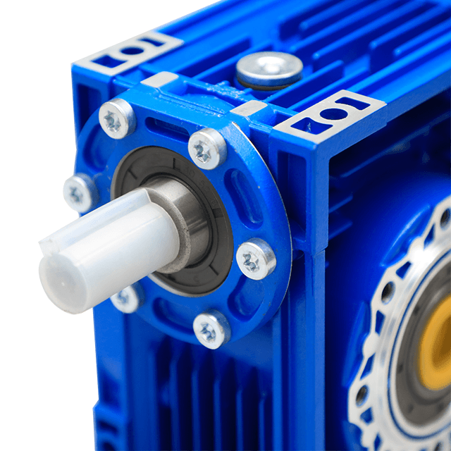
To truly evaluate the durability of a transmission unit, engineers must look under the hood at the materials and structural design. The internal environment experiences high levels of sliding friction. This demands specific metallurgical choices. The input shaft is typically machined from high-alloy steel, case-hardened, and precision-ground. This ensures a smooth surface finish that minimizes drag. Conversely, the wheel is almost exclusively cast from softer bronze or brass alloys.
Why use soft bronze? In the event of extreme friction or lubrication failure, the bronze wheel acts as a sacrificial component. It wears down before the much more expensive steel shaft sustains catastrophic damage. High-capacity taper roller bearings support the shafts against heavy radial loads, while premium oil seals keep lubrication locked securely inside the housing.
When discussing contemporary power transmission, the NMRV Reducer stands out as the absolute industry standard. Take the NMRV50 model as a prime example. Unlike older bulky cast-iron models, this specific modular design features a square housing made from die-cast aluminum alloy. This material choice offers distinct advantages. It is naturally resistant to rust and significantly lighter, reducing the structural load on machinery frames. Most importantly, it provides exceptional thermal conductivity. Because sliding friction generates considerable heat, the aluminum housing acts as a highly efficient heat sink to protect the internal synthetic oil.
Looking at the broader landscape of industrial automation, the demand for compact and high-efficiency mechanical drives is rapidly evolving. Recent industry analyses indicate a massive shift away from oversized heavy cast-iron drives. The market is aggressively moving toward lightweight modular aluminum units. As factories become increasingly automated, integrating smart sensors into gearboxes to monitor vibration and oil temperature in real-time is shifting from a luxury to a standard expectation.
Global energy costs continue to rise. In response, manufacturers are heavily investing in advanced synthetic lubricants and optimized gear tooth profiles. These innovations directly mitigate the traditional efficiency losses associated with sliding friction. The future of this technology lies in maximizing thermal dissipation while shrinking the physical footprint even further. This miniaturization is absolutely necessary to accommodate the booming robotics and Automated Guided Vehicle sectors.
The combination of high torque, compact design, and self-locking capabilities makes these units highly versatile across numerous heavy-duty sectors. In mining and aggregate processing, conveyor systems rely on a Right Angle Gearbox configuration to sit completely parallel to the conveyor frame. This saves critical aisle space while providing the massive starting torque required to move tons of raw material. Hoisting and lifting machinery, such as industrial winches, utilize the self-locking feature to ensure suspended loads remain securely in place during unexpected power outages.
While heavy industry relies on brute force, precision technology demands a completely different approach. Miniaturized versions of these drives have carved out a significant niche where spatial constraints are rigorous. In the medical field, adjustable hospital beds and MRI machine positioning tables require smooth jerk-free movement. The continuous sliding action of the gears ensures exceptionally quiet operation. Smart home automation also heavily utilizes these compact drives for automated sliding gates. The non-backdrivable nature prevents intruders from manually forcing the security barrier open.
Selecting mechanical components always requires balancing operational benefits against physical limitations. One of the most significant advantages here is the ability to achieve massive reduction ratios. Standard units easily offer ratios from 7.5:1 all the way up to 100:1 in a single stage. Achieving this level of reduction with helical gears requires multiple stages, drastically increasing both the size and cost of the assembly. Furthermore, these units operate via a continuous sliding motion rather than noisy rolling tooth-on-tooth impact. This results in acoustic-dampening operation ideal for noise-sensitive environments.
To make the best engineering choice, consider this direct comparison of drive types:
| Feature | Worm Drive System | Standard Helical System |
|---|---|---|
| Physical Layout | 90-degree Right Angle | Inline or Parallel Shaft |
| Single Stage Ratio Limit | Up to 100:1 | Typically maxes at 10:1 |
| Self-Locking Ability | Yes at high reduction ratios | No inherent locking |
| Operational Noise Level | Very Low due to sliding action | Moderate to High |
| Thermal Generation | High requires proper venting | Low |
The very feature that makes them quiet is also their biggest engineering limitation. Sliding friction generates substantial heat. This leads to energy loss and lower overall mechanical efficiency. While a premium helical setup might operate at 95 percent efficiency, a high-ratio sliding drive might only achieve 60 to 70 percent efficiency. You may need a slightly larger motor to hit your desired output target. Consequently, they require strict thermal management and premium synthetic gear oils to prevent rapid degradation.
Even the most robustly engineered systems remain subject to wear and tear over thousands of operating hours. Overheating destroys gears. When the unit operates beyond its thermal capacity, the gear oil begins to break down and completely lose its crucial viscosity. Without a protective oil film, metal-on-metal contact occurs, rapidly scoring the internal components. To prevent this, operators must never subject the drive to continuous duty cycles if it is only rated for intermittent use. Always check fluid levels routinely and ensure the breather plug remains clear to allow for heat expansion.
As previously noted, the bronze wheel intentionally acts as the sacrificial component. Yet, if the teeth wear down rapidly, you have a severe systemic issue. You will notice heavy bronze shavings in the oil or a sudden increase in output shaft backlash. This rapid degradation is typically caused by severe shock loading or starting the motor under an excessively heavy load. Implementing soft-starters or Variable Frequency Drives can eliminate violent shock loads during startup. This simple electrical upgrade significantly extends mechanical lifespan.
Lubricant escaping from the input or output shafts serves as a clear indicator of seal failure. Thermal cycling causes extreme internal pressure fluctuations. Over time, this pressure combined with abrasive environmental dust degrades the rubber oil seals. Routinely inspect the aluminum housing for oil seepage. If you detect a leak, replace the affected seals immediately. A clogged vent plug is often the hidden culprit behind sudden leaks. Trapped pressurized air will inevitably force hot oil out through the weakest rubber barrier.
Procuring the correct mechanical drive is never a matter of guesswork. It is a strict mathematical calculation. Selecting an undersized unit guarantees rapid failure. Oversizing wastes valuable factory space and capital budget. Before approaching a vendor, you must define three exact parameters. First, identify the input speed of your driving motor, which is commonly 1400 RPM or 1750 RPM. Second, determine your required reduction ratio based on how fast you need your final application to move. Finally, calculate the exact output torque required to move your specific load.
Mathematical torque calculations only represent ideal laboratory conditions. Real-world industrial environments are rarely ideal. Engineers must apply a Service Factor multiplier to account for operational stress. A machine running less than 8 hours a day with smooth operation might only require a Service Factor of 1.0. Conversely, a rock crusher running continuously with heavy impact loads demands a Service Factor of 1.75 or higher. Ambient temperature also dictates your choice. Units operating in freezing outdoor environments require specialized seals and temperature-specific lubricants.
The internal metallurgy and machining precision ultimately dictate the longevity of your entire transmission system. Sourcing equipment from unverified vendors often leads to acquiring units with poor-quality bronze alloys or misaligned housings. For engineers seeking durable factory-direct solutions, exploring precisely engineered Worm Gearbox solutions ensures you receive equipment capable of handling demanding loads. Always consult with the manufacturer engineering team to verify that your calculated service factors align perfectly with your chosen model.
This specialized gearing system remains an absolute indispensable tool for modern industrial automation. It provides exceptional torque multiplication and saves highly valuable floor space through its compact right-angle design. Proper lubrication and strict thermal management are non-negotiable. However, the inherent self-locking ability and immense cost-effectiveness make these drives incredibly difficult to replace with alternative technologies. Accurately calculating your specific load requirements guarantees decades of reliable power transmission. Ready to upgrade your machinery? Evaluate your mechanical systems today and explore the high-performance aluminum NMRV series at Huake Gearbox to find the exact specifications required for your next heavy-duty project.
Generally, no. Due to the steep friction angle between the gear teeth, most high-ratio configurations are considered non-backdrivable. While the motor can drive the input shaft to turn the output, applying rotational force to the output shaft will not turn the motor. This built-in braking effect is highly desirable in lifting and inclined conveying applications to prevent load drops.
The primary differences lie in material construction, weight, and modularity. An NMRV model utilizes a square-shaped die-cast aluminum alloy housing. This makes it significantly lighter, completely resistant to surface rust, and capable of dissipating internal heat much faster than traditional cast iron. The square design also allows for highly flexible omnidirectional mounting on the factory floor.
These units require highly specific lubrication due to the sliding friction between the steel shaft and the softer bronze wheel. You must use compounded gear oils containing friction modifiers or fully synthetic Polyalphaolefin or Polyalkylene Glycol based lubricants. Never use standard automotive motor oil or Extreme Pressure gear oils containing active sulfur. The chemical additives in standard EP oils will actively corrode and destroy the bronze gear.
No. While they are the most common and cost-effective type of right-angle drive, bevel gearboxes also operate at a 90-degree angle. Bevel gearboxes offer much higher mechanical efficiency and do not suffer from the same severe heat generation issues. However, they are generally much more expensive and cannot achieve the massive single-stage reduction ratios like 60:1 or 100:1.
The lifespan is entirely dependent on proper sizing, application environment, and preventative maintenance. If the drive is correctly sized for the load, protected from severe mechanical shock, and subjected to strict oil changes using the correct synthetic lubricant, the housing and steel shaft can last for decades. The bronze wheel is a wear part and will eventually require replacement.
To find your required ratio, simply divide the input speed of your motor by your desired output speed. For example, if you are using a standard 1400 RPM electric motor and your conveyor belt drive shaft needs to turn at 35 RPM, you divide 1400 by 35. This calculation results in 40. Therefore, you need to select a gearbox with a 40:1 reduction ratio.
Unlike standard spur gears that roll against each other, these mechanisms rely on a continuous sliding friction to transmit power. This sliding action inherently generates a significant amount of thermal energy. It is completely normal for the exterior aluminum housing to feel hot to the touch during continuous operation. This is exactly why using high-quality synthetic oil and ensuring the breather plug is unobstructed is critical for heat management.


