- All
- Product Name
- Product Keyword
- Product Model
- Product Summary
- Product Description
- Multi Field Search


Views: 0 Author: Site Editor Publish Time: 2025-09-23 Origin: Site


Choosing the right gear ratio for a gearmotor or reducer can feel confusing at first. Torque, speed, and efficiency all depend on this single factor. A poor choice may lead to wasted energy, extra wear, or even system failure. The right choice, however, ensures smooth performance and longer equipment life.
In simple terms, the gear ratio tells us how many times the motor must turn to move the output shaft once. A higher ratio means more torque but slower speed. A lower ratio means faster speed but less torque. Knowing how to balance these two is the key.
This guide will explain what gear ratio means, why it matters, and how to select the best ratio for your application. We’ll cover common formulas, examples, and tips engineers use every day so you can make the right decision without guesswork.
A gear ratio shows how input speed compares to output speed in a gearmotor or reducer. It tells us how many turns of the motor shaft make the output shaft rotate once. Understanding how to choose the gear ratio for a gearmotor or reducer ensures your system runs efficiently.
High gear ratio: More torque, slower speed
Low gear ratio: Less torque, faster speed
Different gear types affect ratios:
Spur gears: Simple, efficient
Helical gears: Quieter, smoother
Planetary gears: Compact, high torque
Worm gears: Big ratio in small space
| Gear Ratio | Output Speed | Torque |
|---|---|---|
| 5:1 | Slower | Higher |
| 10:1 | Slower | Much Higher |
| 2:1 | Faster | Lower |
They influence motor behavior, efficiency, and lifespan. Choosing the right gear ratio is about balancing speed and torque, which is exactly what engineers consider when choosing the gear ratio for a gearmotor or reducer.

First, determine how fast your application must move by measuring in RPM. Conveyor belts typically need moderate speed to efficiently transport materials, while robotic arms require precise, slower motion for accurate positioning. On the other hand, high-speed tools need lower torque but faster movement to perform tasks like cutting or drilling. To select the appropriate gear ratio for a gearmotor or reducer, use the formula: Gear Ratio = Motor RPM ÷ Desired Output RPM. This calculation is crucial for matching the motor’s speed to your application’s requirements.
Torque is essential for driving motion and overcoming resistance. Higher torque is necessary to start and move heavy loads. To calculate the required torque at the output, use the formula: Torque_out = Torque_motor × Gear Ratio. It’s important to consider startup torque, which is often higher than running torque, to ensure the motor can handle the initial load. Avoid undersizing the motor, as this can lead to excessive stress and potential damage.
Understanding your load type is vital for selecting the right gear ratio. Constant loads maintain steady speed and predictable torque, making them easier to manage. Variable loads, however, experience changes in speed and torque, which may require additional buffering to maintain performance. Shock loads involve sudden spikes in force, necessitating a safety factor to protect the motor and gear system from damage. These insights help in choosing the appropriate gear ratio for a reducer or gearmotor to ensure reliable operation.
Motor specifications are critical for ensuring compatibility and performance. Check the nominal speed and torque to ensure they align with your application’s requirements. Review the efficiency curve to understand how the motor performs under different loads. Additionally, be aware of the maximum continuous and peak torque capabilities to avoid overloading the motor. Ignoring these specs can lead to overheating or motor burnout. Understanding these limits is essential when learning how to choose the gear ratio for a gearmotor or reducer.
Space limitations can impact gearmotor selection. Large gear ratios may require larger gears, which can be challenging to fit into compact spaces. Planetary gears or worm gears are often used to achieve high ratios without significantly increasing the size of the gearmotor. These gear types allow you to maintain high torque output without compromising on space, making them ideal for applications with tight size constraints.
Environmental conditions can significantly affect the performance and longevity of gearmotors. High temperatures can reduce the life of lubrication, while dust and moisture can accelerate wear and corrosion. Vibration can also cause parts to loosen over time. Proper sealing, housing, and gear material selection are crucial for ensuring the durability and reliability of the gearmotor in harsh environments. These factors play a significant role in gear ratio selection for gearmotors and reducers, as they influence the overall design and maintenance requirements.
1. Measure desired output speed
2. Calculate needed torque
3. Divide motor speed by output speed
4. Multiply motor torque by ratio for output torque
5. Check safety factor (1.2–1.5× recommended)
| Motor RPM | Desired Output RPM | Gear Ratio | Motor Torque (Nm) | Output Torque (Nm) |
|---|---|---|---|---|
| 1500 | 300 | 5:1 | 2 | 10 |
| 1200 | 60 | 20:1 | 1.5 | 30 |
Using charts or calculators helps verify your work. These tools make choosing the gear ratio for a gearmotor or reducer easier and more accurate.
Overestimating torque → Oversized, expensive gears
Choosing too high ratio → Sluggish speed
Ignoring motor efficiency → Wastes energy
Not considering multi-stage effects → Extra complexity
Checklist:
Check motor curves
Consider shock loads
Balance speed and torque
Mind space constraints
Avoiding these mistakes improves results when selecting the right gear ratio for a gearmotor or reducer.
In a conveyor system, the goal is to achieve moderate speed and moderate torque to efficiently transport materials. Gear ratios typically range from 5:1 to 10:1, which are well-suited for maintaining a steady pace without excessive wear. Helical or planetary gears are often used due to their efficiency and ability to handle continuous operation. For example, a manufacturing plant might use a conveyor system with a 7:1 gear ratio to move parts along the assembly line smoothly and reliably. This example demonstrates how understanding the specific requirements of an application can guide the selection of the appropriate gear ratio for gearmotors and reducers.
Robotic arms require slow, precise motion and high torque to perform delicate tasks with accuracy. Gear ratios in this application typically range from 20:1 to 50:1, which provide the necessary power and control. Planetary gears are often preferred due to their compact size and high torque capacity, making them ideal for the limited space within robotic joints. For instance, a robotic arm used in a medical laboratory might have a 30:1 gear ratio to ensure precise movement during sensitive procedures. This illustrates the importance of selecting a gear ratio that matches the specific operational demands of the equipment.
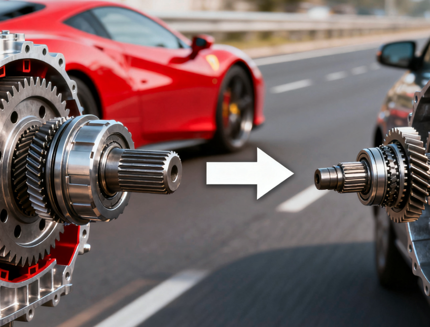
In automotive applications, the challenge is to balance torque and speed to achieve optimal performance. The gear ratio depends on whether the focus is on acceleration or fuel efficiency. Multi-stage gearboxes are common to provide a range of ratios for different driving conditions. For example, a sports car might have a lower gear ratio for rapid acceleration, while a fuel-efficient vehicle might have a higher gear ratio to maximize efficiency at cruising speeds. This example shows how the selection of gear ratios is tailored to meet the specific performance goals of the vehicle, whether it’s speed or efficiency.

When optimizing gear ratio selection for gearmotors and reducers, several practical tips can ensure efficiency and reliability:
Consult Manufacturer Specs: Always refer to the manufacturer’s specifications for the gearmotor and reducer. These documents provide critical information on the maximum and minimum gear ratios, torque capacities, and operational limits.
Account for Future Load Changes: Consider potential changes in load requirements over time. If the application might handle heavier loads in the future, selecting a gear ratio that can accommodate these changes will save on future upgrades.
Test with Prototypes or Simulations: Whenever possible, test the selected gear ratio using prototypes or simulations. This allows you to observe the performance in a controlled environment and make adjustments before full-scale implementation.
Factor in Maintenance and Longevity: Consider the maintenance requirements and expected lifespan of the gearmotor. A gear ratio that minimizes wear and tear will reduce maintenance costs and extend the life of the equipment.
Keep Safety Factor in Calculations: Always include a safety factor in your calculations to account for unexpected loads or operational conditions. This ensures that the gearmotor can handle occasional spikes in demand without failure.
By applying these tips, you can ensure that the gear ratio selection for gearmotors and reducers is not only efficient but also reliable, providing long-term performance and minimizing the risk of mechanical failure.
Motor may overheat, output too slow, torque insufficient.
Only if gearbox allows; otherwise, replacement needed.
Yes. They split reduction across stages for higher ratio.
Yes. 5:1, 10:1, 20:1 often appear in conveyors, robotics, vehicles.
Choosing the right gear ratio isn’t just about formulas—it’s about knowing your application, balancing torque and speed, and avoiding costly mistakes. Whether you’re powering a conveyor, fine-tuning a robotic arm, or designing for automotive use, the right decision determines performance and efficiency.
If you’re still unsure, don’t guess—work with experts who understand the details. Qingdao Chinese Science Machinery Co., Ltd. provides reliable gearmotors and reducers, along with guidance to help you select the perfect ratio for lasting results.