
- All
- Product Name
- Product Keyword
- Product Model
- Product Summary
- Product Description
- Multi Field Search


Views: 0 Author: Site Editor Publish Time: 2026-10-14 Origin: Site


Does your gearbox fit the machine’s installation conditions? Space alone does not determine reliable performance. A Bevel Gear Reducer connects power across different shaft directions. Its mounting, lubrication and support requirements deserve equal attention. You’ll learn how to match these factors to your machine’s layout and operating needs.
A right-angle gearbox can position the motor beside equipment instead of extending along its driven shaft. This arrangement helps designers work around conveyor frames, processing equipment and nearby structures. HUAKE identifies right-angle output among its K-series features. Compare the complete assembly, including guards, cables and maintenance clearance, before approving the layout.
A foot-mounted bevel gear reducer transfers its weight and housing reaction loads into the supporting base. The base needs suitable stiffness and flatness to support accurate alignment. Uneven mounting surfaces can distort the assembly when bolts are tightened. Check mounting dimensions, fastening requirements and connection alignment against the approved installation drawing.
A flange-mounted bevel gear reducer connects through a defined machine interface. This can simplify integration where a separate mounting platform is inconvenient. Check the locating diameter, bolt pattern and supporting housing before assembly. The interface must accommodate the reducer’s weight, attached motor and operating forces without excessive movement.
A hollow-shaft bevel gear reducer can connect directly to a compatible driven shaft. It may reduce separate coupling components where the selected configuration supports this arrangement. Check shaft fit, connection details and torque-reaction support together. Follow the exact model’s instructions because unsuitable restraints can introduce additional bearing loads.
Changing the housing orientation can change how lubricant reaches gears and bearings. A vertical installation therefore needs more than sufficient physical clearance. Confirm the approved mounting-position designation before ordering or repositioning the drive. Check lubricant quantity, seals, breathers and any additional provisions required for that configuration.
Environmental conditions affect the installation’s sealing, surface protection and cooling requirements. Identify dust exposure, moisture sources and nearby heat before choosing the configuration. Request suitable documentation for the proposed environment rather than assuming general industrial suitability. Preserve access so operators can inspect seals, clean surfaces and detect leakage.
Tip:Include the installed orientation and surrounding equipment in every reducer layout drawing.
The bevel stage redirects rotation between intersecting shafts within the transmission. This allows suitable configurations to connect motors and equipment across different shaft directions. Shaft arrangement and housing orientation describe different installation features. A right-angle output does not mean the gearbox can operate in every physical position.
Additional reduction stages help match motor speed to the driven machine’s requirements. HUAKE’s K-series descriptions identify assemblies incorporating helical and bevel gearing. Buyers should compare complete gearbox ratings at the intended ratio and operating point. Series-wide efficiency statements alone cannot establish performance for every proposed installation.
Output connections transmit torque and may introduce other forces into the reducer. Pulleys, sprockets and attached equipment can create radial or axial loads. Their distance from the housing also matters during assessment. Check allowable forces for the selected model instead of relying only on its rated output torque.
Begin with the machine’s required output speed and operating torque. Record startup demands, operating hours, reversals and expected load changes. Apply the supplier’s service-factor method to the complete duty description. Verify peak events separately where acceleration, blockage or process changes create unusually high loads.
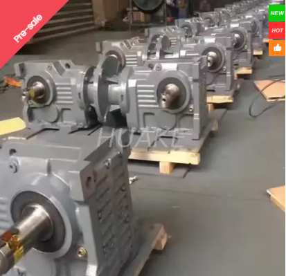
Provide drawings showing the motor, gearbox, driven shaft and surrounding structure. Identify critical shaft dimensions, flange interfaces and mounting-hole positions. HUAKE’s K87 gear motor provides one starting point for configuration discussions. Request the exact assembly drawing before confirming dimensions or installation compatibility.
Identify which components support the gearbox’s weight and resist its reaction torque. Review the driven shaft’s bearing arrangement alongside the proposed mounting method. Adding more restraints can create conflicting forces rather than improve support. Use the manufacturer’s approved arrangement for the exact gearbox and machine connection.
Check motor power, input speed, flange dimensions and connection details together. Include the motor’s position and weight in the structural review. Variable-speed operation also needs assessment across the intended load profile. Confirm the complete combination rather than choosing a motor solely through its nominal power rating.
The following table helps translate installation conditions into purchasing requirements.
| Installation condition | Potential configuration | Main verification |
|---|---|---|
| Restricted machine space | Right-angle drive arrangement | Complete assembly envelope and access |
| Rigid supporting platform | Foot-mounted configuration | Base flatness, stiffness and alignment |
| Suitable equipment interface | Flange-mounted configuration | Locating dimensions and support loads |
| Direct driven-shaft connection | Approved hollow-shaft arrangement | Shaft fit and torque-reaction support |
| Vertical operating position | Approved orientation-specific assembly | Lubrication, seals and breather locations |
| Confined or exposed location | Application-matched configuration | Cooling, protection and maintenance access |
Tip:Specify the mounting method and operating orientation separately when requesting quotations.
The correct lubricant must suit the gearbox configuration and operating conditions. Filling requirements also depend on the approved installed position. Review any proposed orientation change before moving an existing reducer. Confirm whether particular bearings require additional lubrication arrangements under the selected conditions.
Breathers, inspection points and drains need appropriate locations for the installed orientation. Their accessibility also affects routine maintenance quality. A drain hidden behind a machine frame makes servicing unnecessarily difficult. Review these features during layout approval, before guards and neighboring equipment restrict access.
A gearbox can fit physically while lacking adequate space for heat removal. Evaluate ambient temperature, airflow and nearby process heat under representative operation. Mechanical torque capacity and thermal suitability require separate checks. Ask whether the planned operating schedule needs additional cooling or a different configuration.
Tip:An orientation change requires a lubrication review even when the shaft connections remain compatible.
Inspect mounting surfaces for damage, unevenness and contamination before assembly. Check flange interfaces and shaft alignment using the specified procedures. Tighten fasteners according to the approved sequence and requirements. Avoid using bolt force to pull misaligned parts into position, since this can introduce unwanted stress.
Keyed connections, shrink discs and other systems need their own assembly procedures. Confirm engagement length, surface condition and fastening requirements before installation. Use the approved tools to position connected components. Avoid transmitting assembly forces through bearings or other parts unsuitable for those loads.
Verify rotation direction and output speed before connecting the full process load. Increase loading according to the approved commissioning procedure. Observe temperature, vibration, noise and leakage under representative conditions. Record the results so maintenance teams have a useful baseline for later comparison.
New vibration can originate from mounting, alignment or the connected machine. Check fasteners, support rigidity and connection alignment before assuming internal damage. Compare observations at similar speeds and loads. A change appearing only under process load may require reviewing the driven equipment’s resistance.
Check installed orientation, lubricant quantity and breather arrangement when unusual heating develops. Review airflow, ambient conditions and changes in operating load. Inspect seals and nearby connections if leakage appears. Identify the cause before changing lubricant or adjusting operation, since several problems can produce similar symptoms.
Review shaft fit, external forces and torque-reaction support in direct-mounted installations. Compare the actual assembly against the manufacturer’s approved bearing and restraint arrangement. Conflicting supports may impose forces beyond the intended design. Correct the installation cause before replacing damaged components and restarting the equipment.
Tip:Record operating conditions alongside symptoms so troubleshooting compares equivalent loads and speeds.
Request current ratings, dimensional drawings and installation instructions for the exact assembly. Keep bevel, helical-bevel and helical-worm configurations clearly identified during comparisons. HUAKE’s KAT97 gear motor is described within its modular K-series offering. Confirm connection details directly instead of interpreting model letters across suppliers.
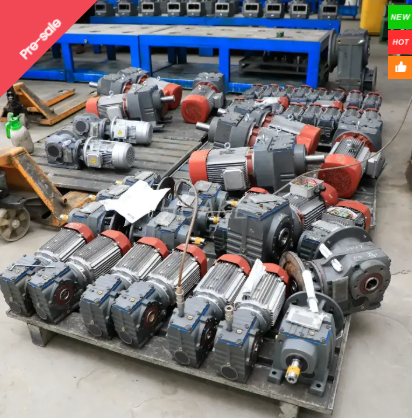
Include the motor, gearbox, connections and supporting structure in each comparison. Account for service clearances, installation work, electricity and routine maintenance. The KAF167 gear motor provides another configuration for discussion. Compare proposals at equivalent output speed, load and duty before evaluating overall value.
Agree on dimensional, operational and thermal acceptance requirements before delivery. Confirm shaft loading, mounting position and lubrication instructions within the approved documentation. Retain drawings and commissioning records alongside maintenance information. If the machine design changes, review the reducer configuration before accepting the revised arrangement.
A Bevel Gear Reducer supports varied installation layouts. Correct sizing, mounting and lubrication help maintain reliable power transmission.
Shaft alignment and structural support also influence performance. Buyers should confirm these requirements before approving the complete assembly.
HUAKE offers modular K-series gear motors. Their motor combinations and installation options help buyers match transmission equipment to machine requirements.
A: A Bevel Gear Reducer reduces speed and redirects power between intersecting shafts.
A: A Bevel Gear Reducer accommodates different layouts through suitable mounting configurations.
A: A Bevel Gear Reducer requires approval and orientation-specific lubrication.
A: Bevel gearbox mounting depends on interfaces and support.
A: Bevel gearbox installation costs include connections and alignment.
A: Check bevel gearbox lubrication, loading and ventilation.


