
- All
- Product Name
- Product Keyword
- Product Model
- Product Summary
- Product Description
- Multi Field Search


Views: 0 Author: Site Editor Publish Time: 2026-10-19 Origin: Site


I have seen countless electric motors burn out simply because they were improperly matched to their driven loads. Standard alternating current motors spin at incredibly high velocities. They frequently operate anywhere from 1,400 to 3,600 revolutions per minute. However, most heavy machinery requires much slower, highly controlled, and significantly more powerful movements to function effectively. Direct-driving an inclined conveyor belt or a massive lifting hoist at those raw motor speeds would violently tear the equipment apart.
This operational gap brings us to a fundamental engineering question. Do these specific mechanical devices actually decrease rotational speed? The definitive answer is yes. They are meticulously engineered to slow down rotation while simultaneously multiplying torque output. By integrating a standard electric motor with a specialized Worm Gear Reducer, facility engineers can achieve the precise mechanical force required for demanding applications. This comprehensive guide breaks down the empirical mechanics behind this process. It explores inherent advantages alongside physical limitations and provides a clear framework to help you specify the exact equipment needed for your next build.
To truly understand how these transmission systems manipulate power, we must look at their internal geometry. The fundamental mechanism involves two primary components. These are the steel worm and the mating wheel. The worm closely resembles a standard threaded screw and is typically machined from hardened carbon steel. This steel component meshes directly with the wheel. The wheel looks like a traditional toothed spur gear but is cast from a softer, sacrificial metal like phosphor bronze.
When the electric motor turns the input shaft, the helical threads rotate. As these threads spin, they aggressively push against the bronze teeth. Because heavy-duty bearings constrain the input shaft, its rotational movement forces the wheel to rotate in a continuous sliding action. The output speed drastically drops because the input shaft must complete multiple full rotations to advance the wheel by just a single tooth.
When calculating mechanical output on a factory floor, the underlying mathematics prove both straightforward and highly effective. In mechanical engineering, this relationship is defined by the gear ratio. If a unit features a single-thread worm and a mating wheel with 40 teeth, the motor must turn the input shaft 40 complete times to make the output shaft complete one full revolution.
This creates a 40 to 1 reduction ratio. Specifically, if your input motor spins at 1,400 revolutions per minute, the output shaft will rotate at exactly 35 revolutions per minute. Through this simple yet ingenious mechanical reduction, engineers gain absolute control over machine operating speeds.
One of the defining architectural characteristics of this setup is its configuration as a Right Angle Drive. In this layout, the input shaft and the output shaft are positioned exactly 90 degrees apart.
This perpendicular orientation offers a massive advantage in industrial facility design. Traditional inline gearboxes require a long footprint, consuming valuable lateral floor space. In contrast, a 90-degree configuration allows the motor to be tucked neatly alongside the machinery chassis. This saves significant space, reduces the overall footprint of the conveyor or packaging machine, and allows for much more compact equipment layouts.
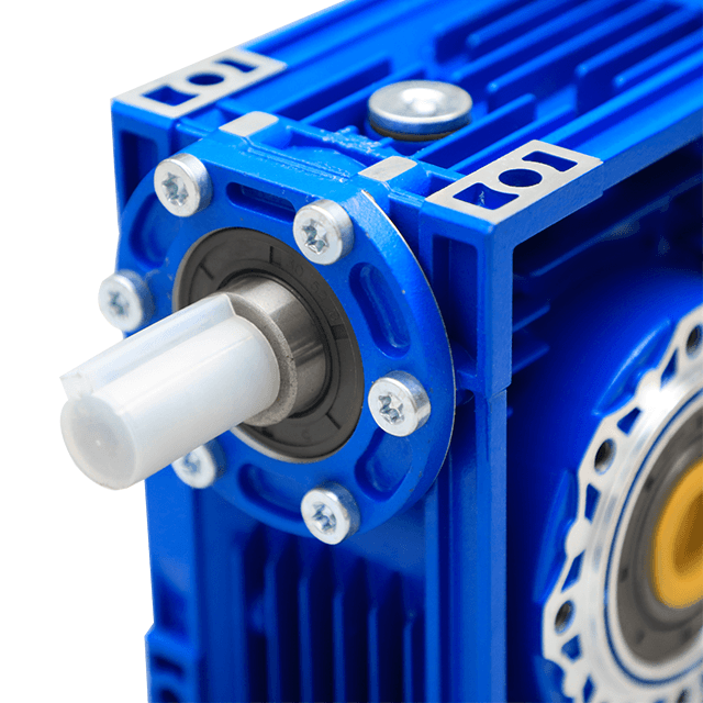
While the industrial market offers a wide variety of transmission systems, this specific style remains an industry staple across global manufacturing. Engineers consistently specify these units for their distinct operational benefits. However, they also come with inherent physical limitations that must be carefully evaluated during the initial design phase.
High Torque Output: The law of conservation of energy dictates that when rotational speed is reduced, rotational force is proportionally increased. Because these units can achieve massive reduction ratios, sometimes up to 100 to 1 in a single stage, they multiply the motor torque exponentially. This makes them the go-to choice for heavy-duty applications like rock crushing, industrial mixing, and heavy material lifting.
The Self-Locking Mechanism: This is arguably the most critical safety feature of high-ratio units. In gearboxes with a reduction ratio of 30 to 1 and above, the lead angle of the thread is exceedingly shallow. Because of this shallow angle and the high coefficient of static sliding friction, the wheel simply cannot force the input shaft to rotate backward. If facility power is suddenly cut, the load cannot backdrive the motor. This acts as an automatic brake for inclined conveyors, preventing thousands of pounds of material from crashing down.
Quiet and Smooth Operation: Unlike spur gears which rely on the rolling action of metal teeth violently engaging, these systems operate via a continuous sliding action. This constant meshing produces significantly less vibration and acoustic noise. Consequently, they are highly desirable in environments where noise pollution must be strictly minimized, such as theater stage lifts and food processing facilities.
Efficiency Loss and Heat: For technical buyers, transparency regarding mechanical efficiency is crucial. The exact same sliding action that makes the unit whisper-quiet also generates substantial internal friction. When hardened steel aggressively slides against softer bronze under heavy loads, that friction inevitably manifests as thermal energy. If you touch one of these units after a long shift, it will be noticeably hot. A significant portion of the input power is lost as heat, making high-ratio units less energy-efficient than their helical counterparts.
Wear and Tear: To prevent the entire transmission system from destroying itself under immense friction, engineers purposefully design the system using dissimilar metals. The bronze wheel acts as a sacrificial component. It is designed to slowly wear away over thousands of hours of operation to protect the much more expensive steel worm. Regular maintenance and the application of specialized synthetic lubrication are absolutely mandatory to manage this wear.
When transitioning from mechanical theory to actual industrial procurement, buyers frequently encounter specific industry standards. Understanding the current trajectory of the power transmission sector is essential for sourcing equipment that will not become obsolete.
As global manufacturing pivots heavily toward lean automation, the power transmission sector is experiencing a massive shift in demand. Facility managers are actively moving away from bulky custom-built cast-iron machinery. Current engineering trends prioritize standardized and modular components. There is a rapidly growing emphasis on lightweight materials, rapid heat dissipation, and plug-and-play designs that minimize machine downtime. Furthermore, strict energy efficiency regulations are pushing plants to adopt highly optimized aluminum housings that manage thermal losses better than legacy steel blocks.
This trend has catapulted specific standardized designs to the forefront of modern engineering. The NMRV Gearbox is currently one of the most universally recognized speed reducers in the industrial landscape. The NMRV designation refers to a highly standardized profile characterized by a distinctive square housing.
Take the popular NMRV50 series as a prime example. Engineered with a 50-millimeter center distance, this unit is constructed from premium die-cast aluminum alloy rather than heavy cast iron. This material choice makes the unit exceptionally lightweight and highly resistant to environmental rust. More importantly, the aluminum fins excel at rapidly dissipating the heat generated by internal sliding friction. The square body design is highly modular, allowing installation technicians to mount the unit upside down, sideways, or vertically without causing oil leaks. These units typically offer standard ratios ranging from 7.5 to 1 up to 100 to 1 in a single stage, covering almost every standard conveyor requirement.
Historically, building a drive system was a tedious process. Engineers had to purchase an electric motor and a standalone gearbox separately. They would then spend hours carefully aligning the two shafts using external couplings. This frustrating process was highly prone to human error, often resulting in severe vibration and premature bearing failure.
Today, the industry standard has firmly shifted toward the integrated Worm Gear Motor. This is a complete assembly where the electric motor is directly flanged and coupled to the reducer right at the factory using standard mounting flanges. Purchasing a combined unit completely eliminates shaft alignment issues, drastically reduces installation time on the factory floor, and ensures perfect mechanical compatibility.
When specifying a drive system, engineers frequently debate whether to utilize a sliding mesh drive or a helical drive. Neither technology is universally superior. The correct choice depends entirely on the specific empirical requirements of your application.
Below is an objective comparison to assist in technical decision-making:
| Feature / Specification | Worm Gear Reducer | Helical Gear Reducer |
|---|---|---|
| Mechanical Efficiency | Lower, 50% to 90%, heavily dependent on ratio | Very High, Typically 90% to 98% |
| Initial Cost | Highly affordable, excellent cost-to-torque ratio | Generally more expensive to manufacture and purchase |
| Form Factor | Compact, 90-degree perpendicular layout | Typically inline unless using costly bevel-helical configurations |
| Self-Locking Ability | Yes, inherent safety feature in high ratios | No, always requires external mechanical braking systems |
| Noise Levels | Very quiet due to smooth sliding friction | Slightly louder due to rolling tooth engagement |
| Shock Load Tolerance | Excellent, softer bronze naturally absorbs sudden impacts | Moderate, rigid steel teeth can chip under severe stress |
Verdict: If your application requires continuous operation where minimizing electricity consumption is a major financial factor, a helical gearbox is the better long-term investment. However, if you are constrained by tight physical space, working with a strict project budget, or require inherent self-locking capabilities for intermittent hoisting, the sliding-mesh drive is the definitive engineering choice.
A frequent question found on mechanical engineering forums is whether a gearbox can be run in reverse to increase speed rather than reduce it. In theory, applying power to the output shaft of a standard gear train will spin the input shaft much faster.
However, with this specific mechanical design, the concept of backdriving usually fails miserably. If you attempt to apply massive rotational force to the bronze wheel in an attempt to drive the steel worm, the physics of the thread angle and the high coefficient of static friction will actively fight the movement. Pushing against the shallow thread merely wedges the gear teeth harder against the steel.
In very low-ratio configurations, it might be marginally possible to backdrive the unit, but it will be violently inefficient and generate massive amounts of heat. In high-ratio setups, the self-locking nature of the geometry makes it physically impossible. The internal components will simply bind up and lock. Forcing the rotation via heavy machinery will result in catastrophic mechanical failure, instantly shearing the teeth right off the bronze gear. Therefore, they should strictly be utilized for speed reduction.
Choosing the correct industrial hardware is a critical decision that dictates the lifespan of your machinery. Selecting an undersized unit will lead to rapid premature failure, while oversizing wastes valuable capital and space. Follow these technical steps to ensure you specify the proper Speed Reducer for your build.
The very first step is establishing your target output speed. You must know the operating revolutions per minute of your electric motor and the required speed of your driven machinery. Divide the motor speed by the target output speed to find your required gear ratio. For instance, if your motor spins at 1,400 revolutions per minute and your conveyor belt drive shaft needs to turn at 28 revolutions per minute, you require exactly a 50 to 1 ratio.
Speed is only half the equation. You must ensure the unit can physically handle the load without stripping the internal gears. Calculate the running torque required to move your load, but more importantly, calculate the starting torque. Jerking a heavy load from a dead stop requires significantly more force than keeping it moving in a steady state. Ensure the rated output torque of the gearbox exceeds your maximum starting torque. Always incorporate a standard service factor, typically between 1.2 and 1.5, to account for unexpected shock loads and daily operational stress.
The physical environment heavily dictates the materials and maintenance schedule of your unit. For standard indoor manufacturing facilities, a lightweight aluminum NMRV unit is perfect. However, if the unit will be exposed to harsh corrosive chemicals or high-pressure washdowns in a meat packaging plant, you may need a heavy-duty cast-iron housing treated with specialized anti-corrosion epoxies. Additionally, ensure the input flange matches your motor frame size exactly to guarantee seamless integration.
In summary, utilizing a sliding mesh mechanism remains one of the most reliable, compact, and highly cost-effective methodologies for slowing down a high-speed electric motor while simultaneously multiplying its torque. By taking advantage of this simple yet ingenious geometry, engineers are provided with immense mechanical advantage wrapped inside a quiet and space-saving footprint.
Whether your upcoming project requires a simple perpendicular configuration to save floor space, or a fully integrated motor-and-gearbox assembly for rapid plug-and-play installation, understanding the underlying mechanics ensures you make a sound engineering choice. Always factor in thermal efficiency, starting torque requirements, and environmental operating conditions before finalizing your purchase.
If you are upgrading your facility or designing a new automated system, sourcing reliable transmission equipment is non-negotiable. We highly recommend evaluating your specific torque and spatial requirements, and exploring the premium standard and custom solutions available directly from Huake Gearbox to guarantee years of trouble-free, high-efficiency operation.
In a standard single-stage configuration, reduction ratios typically range from 5 to 1 on the low end up to 100 to 1 on the high end. If an industrial application requires even slower and more precise speeds, engineers can connect two gearboxes together in a series. This is known as a double-reduction setup and can achieve massive ratios such as 3,000 to 1 or higher, though mechanical efficiency drops significantly in these complex setups.
The fundamental operating principle of these devices relies entirely on a steel thread sliding aggressively against bronze teeth. Unlike rolling friction found in other gear types, sliding friction creates a high degree of mechanical resistance. This resistance is naturally converted into thermal energy. This heat generation is entirely normal. Proper sizing, adequate ambient airflow, and the use of high-quality synthetic lubricants are essential to safely dissipate this heat and protect the internal components.
This depends strictly on the specific gear ratio and the safety requirements of the application. High ratios, usually 30 to 1 and above, possess a very shallow thread lead angle, making them inherently self-locking. This means the suspended load cannot drive the motor backward. However, for critical lifting applications involving human safety or extremely heavy suspended loads, external mechanical braking systems are still strictly mandated to comply with global safety regulations.
In everyday industrial terminology, the two terms are frequently used interchangeably. A gearbox is simply a broad overarching term for any enclosed system of gears used to transmit power. A speed reducer is a specific sub-category of a gearbox that is engineered primarily to decrease the input speed from a power source while simultaneously increasing the output torque.
The lifespan of these units depends heavily on the duty cycle and maintenance schedule. Because the bronze wheel is a sacrificial component designed to absorb wear, it will eventually degrade. However, with proper initial sizing, strict adherence to load limits, and regular oil changes, a high-quality unit can easily operate flawlessly for tens of thousands of hours before requiring a replacement gear set.
Standard mineral oils often break down rapidly under the intense heat generated by sliding friction. Therefore, industrial engineers strongly recommend using premium synthetic polyglycol lubricants. These specialized synthetic oils maintain their viscosity at much higher operating temperatures, significantly reducing wear on the bronze teeth and extending the overall operational life of the equipment.


