
- All
- Product Name
- Product Keyword
- Product Model
- Product Summary
- Product Description
- Multi Field Search


Views: 0 Author: Site Editor Publish Time: 2026-08-17 Origin: Site


Modern multi-axis CNC machining requires rigid, high-fidelity motion transmission. You need this mechanical stability to achieve sub-micron tolerances. Perfect surface finishes demand absolute control over every moving axis. Standard gearheads repeatedly fail under heavy dynamic loads. They introduce unacceptable backlash and structural compliance. These mechanical weaknesses lead directly to tool chatter and positioning errors. Such failures generate high scrap rates and missed production schedules. We designed this framework for engineering and technical procurement teams. It provides a strict, evidence-based approach for evaluating motion systems. You will learn how to size and select a precision planetary gearbox for demanding applications. We focus on mechanical rigidity, thermal management, and proper inertia matching. You can build highly reliable CNC architectures by following these guidelines.
A CNC machine executes precise tool paths based on digital commands. However, mechanical realities often distort these theoretical paths. How your transmission handles torque dictates final part quality.
We must address surface finish and chatter mitigation first. Torsional stiffness directly correlates to maintaining exact tool positions. Cutting forces fluctuate violently during heavy milling operations. Low gearbox stiffness acts just like a mechanical spring. It compresses and releases under varying loads. This compliance induces severe vibration at the cutting tool. We refer to this vibration as chatter. Chatter destroys surface finishes and shatters carbide end mills. High torsional rigidity prevents this deflection entirely.
Reversal error presents another massive challenge. Any lost motion during an axis reversal creates physical deviations. We define this unacceptable gap as backlash. Standard backlash ruins circular interpolation tasks. It leaves visible witness marks on machined quadrants. Differentiating between standard and micro-backlash is essential. Standard units work for simple material handling. High-end contouring demands micro-backlash limits. You must eliminate reversal errors to execute flawless arcs.
Dynamic response rates also separate average machines from elite ones. CNC programs constantly command high-G acceleration and rapid deceleration. Heavy internal components resist these speed changes. A lightweight internal gearset improves the dynamic response significantly. It allows the servo to accelerate the load instantly. The machine can execute rapid moves without overshooting the target coordinate.
Engineers must evaluate specific mechanical metrics during the design phase. These metrics predict how the unit behaves under continuous stress.
We classify gearboxes primarily by their backlash ratings. Establishing strict baselines prevents poor component selection. Standard classes generally operate below 8 arc-minutes of play. Precision classes stay firmly below 3 arc-minutes. Ultra-precision units hold tolerances under 1 arc-minute.
You must also account for lifecycle degradation. Mechanical wear naturally increases internal clearances over time. You should select designs incorporating wear-compensating features. Some manufacturers utilize optimized tooth profiles to minimize wear. We recommend reviewing these common mistakes during selection:
Rigidity defines a unit's resistance to physical twisting. We evaluate stiffness metrics using Newton-meters per arc-minute (Nm/arcmin). High rigidity prevents wind-up under peak torque delivery. It keeps the servomotor in perfect sync with the load.
You also need robust radial and axial bearing ratings. Heavy overhung loads constantly stress the output shaft. Rack-and-pinion drives and heavy ballscrews require massive support. Assessing the output bearing configuration is mandatory. Tapered roller bearings often handle these severe forces best. They distribute heavy loads across a larger contact area.
Table 1: Output Bearing Configurations and CNC Load Ratings
| Bearing Configuration | Axial Load Capacity | Radial Load Capacity | Ideal CNC Application |
|---|---|---|---|
| Deep Groove Ball Bearing | Low | Moderate | Light-duty Z-axis actuators |
| Angular Contact Bearing | Moderate | High | Medium-duty ballscrew drives |
| Tapered Roller Bearing | Very High | Very High | Heavy rack-and-pinion gantries |
High continuous speeds generate significant internal friction. Friction quickly creates heat inside the sealed enclosure. You must evaluate efficiency ratings carefully. High-end units typically exceed 95% operational efficiency.
We must differentiate between continuous and intermittent duty cycles. Intermittent applications allow heat to dissipate during pauses. Continuous high-speed routing pushes thermal limits aggressively. Thermal expansion risks threaten overall machine accuracy. Excessive heat expands internal metal components. This expansion artificially increases friction and degrades lubrication viscosity. It alters precision and forces the servomotor to draw more current.
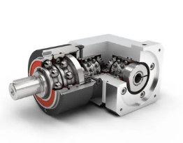
Space constraints strictly dictate modern CNC architecture. Gantries, rotary tables, and automatic tool changers leave little room. You must optimize the mechanical footprint without losing torque.
Evaluating in-line versus right-angle configurations is your first step. In-line models transmit power straight through the axis. Right-angle models use bevel gears to turn the power 90 degrees. A compact planetary reducer helps fit high torque into confined envelopes. Right-angle units save valuable longitudinal space behind the motor. However, they sometimes introduce slightly more backlash due to the bevel stage.
Output configurations heavily influence system rigidity. You must decide between smooth shafts, keyed shafts, and ISO flange outputs. Keyed shafts often introduce micro-play over millions of cycles. Smooth shafts use friction shrink discs for a tighter grip. Flange outputs generally offer the highest torsional stiffness. They allow you to bolt the load directly to the gearbox face. They also create a much shorter mechanical footprint.
Weight considerations heavily impact overall machine dynamics. Gearbox mass affects moving elements like Z-axis rams. Heavy units increase the total inertia of the gantry system. This forces the linear servo motors to work much harder. You must optimize the power-to-weight ratio for all moving components.
Catalog specifications do not guarantee field success. Implementation realities introduce several engineering risks during machine assembly.
Inertia mismatch stands as a primary failure mode. You risk selecting a unit that fails to balance load inertia. You must match the load inertia closely with the motor inertia. Engineers typically target a 5:1 to 10:1 ratio for CNC axes. This ratio ensures highly responsive and stable motion. An improper ratio destabilizes the servo control loop. The machine will shake and oscillate during rapid indexing.
Mounting and alignment vulnerabilities also cause frequent problems. Improper servo motor installation ruins internal bearings quickly. Misaligned motor shafts induce severe radial stress on the input stage. Incorrect collar clamping allows the motor shaft to slip under load. These assembly errors cause premature bearing failure and excessive operating noise.
Lubrication and maintenance demand careful planning. You must assess sealed-for-life designs against oil-bath configurations. Sealed units use advanced synthetic grease and require minimal maintenance. Vertical orientations introduce distinct operational risks. Gravity pulls oil or grease against the lower output seals. You must identify the risk of seal degradation early. An industrial planetary gear reducer operating vertically needs reinforced sealing technology. Dual-lip seals prevent dangerous fluid leaks onto the machining bed.
We need a systematic method for vendor selection. Randomly picking parts from a generic catalog leads to rapid failure. You must qualify suppliers based on engineering transparency.
Document your exact requirements before reviewing any product catalogs.
Reject vendors that hide their engineering data. They must clearly publish torsional stiffness graphs. They should provide detailed efficiency curves at actual operating temperatures. You need comprehensive radial and axial load charts. Vague specifications indicate unreliable manufacturing standards. Real engineering requires transparent data.
Modern machine design requires strict digital validation. You need downloadable, highly accurate 3D CAD models. Vendors must provide native sizing software to assist your team. You must validate servo-to-gearbox compatibility prior to issuing a purchase order. Accurate software prevents costly physical design clashes.
Move from technical spec sheet creation to real-world validation. Request application-engineered quotes from your shortlisted manufacturers. Demand they review your specific load calculations.
Sourcing the correct motion components shifts from a localized mechanical decision to a system-wide strategic advantage. It directly dictates the CNC machine's fundamental accuracy and long-term reliability. Every arc-minute of backlash degrades your final product. You must prioritize torsional rigidity, thermal stability, and proper inertia matching.
Advise your engineering teams to finalize their load and inertia calculations today. Engage with technical sales engineers early in your design phase. Use application-specific simulation tools to validate your structural findings. Build your CNC systems on a foundation of proven mechanical integrity.
A: Wood and composite CNC routers often tolerate 3 to 5 arc-minutes of backlash. High-speed metal milling requires tighter tolerances. Metal cutting generally requires ≤3 arc-minutes to prevent noticeable surface defects during interpolation. Looser tolerances cause visible witness marks on hard materials.
A: Intermittent duty relies on peak torque ratings for short bursts. The unit has time to cool down. Continuous duty is strictly thermally limited. It requires evaluating nominal torque and heat dissipation rates. You must manage continuous heat to prevent synthetic lubrication breakdown.
A: Flange outputs allow the load to be bolted directly to the gearbox face. This significantly increases torsional rigidity. It eliminates the need for flexible couplings. Flange designs also save valuable longitudinal space compared to traditional shaft-and-coupling setups.


