
- All
- Product Name
- Product Keyword
- Product Model
- Product Summary
- Product Description
- Multi Field Search


Views: 0 Author: Site Editor Publish Time: 2026-10-20 Origin: Site


Every experienced mechanical engineer understands the appeal of a compact power transmission unit. They are quiet, cost-effective, and provide significant speed reduction in a very small footprint. Yet, relying solely on these benefits without analyzing their mechanical trade-offs can lead to catastrophic system failures. Designing a reliable drive system requires a hard look at the structural limitations of these mechanisms and how they impact real-world industrial applications.
Unlike standard spur or helical designs, this mechanism does not rely on rolling contact. The meshing action between the components involves continuous sliding friction. This constant rubbing generates significant energy loss during power transmission.
High reduction ratios exacerbate this problem dramatically. A low-ratio setup might achieve an acceptable 85 percent efficiency. However, push that ratio up to 100:1, and the Worm Gear Efficiency can plummet below 60 percent. The lost mechanical energy does not just vanish. It converts directly into thermal energy, creating a cascade of secondary engineering challenges.
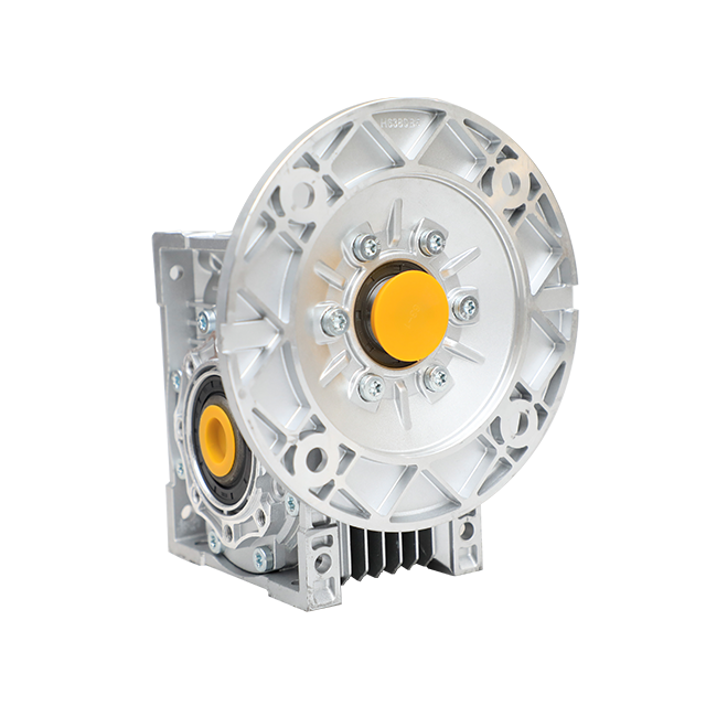
Because of the severe sliding friction mentioned above, managing thermal buildup is a constant battle on the factory floor. In heavy-duty continuous operations, the housing can reach temperatures that rapidly degrade standard mineral lubricants.
Engineers must often specify premium synthetic oils to combat this heat generation. Furthermore, the physical design of the equipment must incorporate cooling fins or utilize a larger housing volume just to shed heat. When specifying an NMRV Gearbox, ensuring proper ambient ventilation in the installation environment is absolutely critical. Poor airflow will inevitably lead to premature oil seal failure and subsequent leaks.
The standard structural design pairs a hardened steel input shaft with a softer bronze alloy wheel. This material mismatch is highly intentional. It prevents the hardened steel shaft from failing, ensuring the softer wheel takes the brunt of the mechanical wear.
Specifically, this means the bronze wheel acts as a sacrificial component. Over thousands of operating hours, microscopic bronze particles shear off and contaminate the internal oil bath. Regular maintenance and strict oil change intervals are non-negotiable. If maintenance teams neglect this, the backlash between the teeth increases rapidly. This excessive play leads to severe positioning inaccuracies in precision lifting or indexing applications.
Many system designers select a Right Angle Gearbox specifically for its static self-locking capability. This prevents a heavy suspended load from driving the motor backward when electrical power is suddenly cut.
In contrast, this exact feature becomes a massive disadvantage in applications requiring manual override or dynamic braking. The transmission system can lock up abruptly during sudden stops, causing severe mechanical shock to the entire drive train. Additionally, these units are strictly limited regarding input speeds. Running them at excessively high RPMs multiplies the sliding friction, leading to rapid thermal runaway and complete gear failure.
Recent developments in industrial automation highlight a clear shift towards strict energy optimization. Rising global electricity costs have prompted plant managers to aggressively scrutinize inefficient power transmission systems on their production lines.
While traditional right-angle drives face stiff competition from highly efficient bevel-helical combinations, the manufacturing sector is adapting rather than abandoning them. Current engineering trends focus on advanced metallurgy and optimized tooth profiles to bridge the efficiency gap. We see a strong move toward hybrid setups. A primary helical stage reduces the motor speed before the final right-angle stage. This hybrid approach significantly minimizes the sliding friction penalty while maintaining the highly desired compact installation footprint.
| Performance Metric | Sliding Friction Drive | Helical/Bevel Drive |
|---|---|---|
| Mechanical Efficiency | 50 to 85 percent depending on ratio | Consistently above 95 percent |
| Wear Rate | High continuous wear on bronze components | Minimal wear due to rolling contact |
| Initial Investment | Highly cost-effective | Significantly higher upfront cost |
| Shock Load Tolerance | Moderate requires careful sizing | Excellent high durability |
Knowing these limitations allows you to choose the right Worm Gear Reducer without compromising system reliability. Do not just estimate the required torque based on motor horsepower. You must calculate the exact output torque and service factor based on your specific duty cycle.
Look at real-world industrial parameters. The standard NMRV series covers center distances from size 025 up to 150. If your application involves intermittent duty, like a packaging conveyor operating only a few times an hour, a standard aluminum alloy housing unit from size 030 to 090 is perfectly adequate.
However, for continuous 24-hour duty with reduction ratios exceeding 60:1, you must upgrade. Consider a larger cast-iron frame size like the 110 or 150. The larger physical volume increases the oil capacity and provides a much larger surface area for heat dissipation. Always verify the input power ratings, which typically range from 0.06 kW for micro-applications up to 15 kW for heavy industrial lifting.
The meshing process relies entirely on sliding friction rather than rolling contact. This continuous sliding action between the hardened steel shaft and the softer bronze wheel acts like a brake pad. It converts a massive portion of the input mechanical energy directly into thermal energy, which must then be dissipated through the housing and oil.
It depends entirely on the lead angle of the internal threads and the total reduction ratio. High-ratio units are typically self-locking and mathematically cannot be backdriven by the load. Low-ratio units might allow backdriving, but the process is highly inefficient and not recommended for machinery requiring smooth, continuous reverse operation.
Lifespan varies completely based on applied load, daily duty cycle, and lubrication quality. With premium synthetic oil and strict operation within the rated torque limits, they can easily last for several years of service. Conversely, overloading the unit or ignoring scheduled oil changes will strip the bronze teeth in a matter of months.
Yes. Hypoid or bevel-helical gearboxes offer the exact same right-angle mounting configurations but utilize rolling friction. These advanced designs achieve mechanical efficiencies well above 90 percent, even at extreme reduction ratios. The trade-off is that they come at a noticeably higher initial purchase cost and lack the inherent self-locking safety feature.
Understanding the mechanical limitations of sliding friction is the very first step to designing a bulletproof power transmission system. The ultimate engineering key is matching your specific operational demands with the correct internal gearbox architecture.
If you need to balance limited installation space, tight project budgets, and reliable performance, selecting the optimal Worm Gear Motor requires precise calculation rather than guesswork. Evaluate your exact torque requirements, daily duty cycles, and ambient environmental conditions carefully. For robust, precisely engineered solutions tailored to your specific industrial needs, explore the comprehensive range of reduction drives at Huake Gearbox to find the exact performance parameters that align with your heavy-duty project goals.


