
- All
- Product Name
- Product Keyword
- Product Model
- Product Summary
- Product Description
- Multi Field Search


Views: 0 Author: Site Editor Publish Time: 2026-10-16 Origin: Site


Power transmission across intersecting axes presents a classic mechanical challenge. When layouts require a 90-degree directional change, engineers rely on specialized gearing. The most basic configuration features teeth cut straight across the pitch cone. The engagement happens all at once across the entire tooth face. This sudden contact creates a distinct impact. Impact inevitably leads to noise and vibration.
Therefore, engineers restrict these components to low-speed applications. Think of manual hand-crank mechanisms or slow-moving agricultural equipment. They are highly cost-effective but struggle under high-speed dynamic loads. If your design runs below 1000 RPM and acoustic output is not a primary concern, a Straight Bevel Gear offers a budget-friendly and reliable solution.
Specifically designed for demanding industrial environments, these gears feature curved, oblique teeth. The mesh begins at one end of the tooth and smoothly travels to the other. This gradual engagement drastically reduces vibration. It allows for much higher operating speeds and significantly heavier load capacities.
From a practical engineering standpoint, this is where premium performance lies. Take the Huake K-Series K87 as a benchmark. This specific unit utilizes advanced spiral tooth profiles to achieve an output torque of up to 2700 Nm. The transmission efficiency consistently exceeds 95 percent. When building continuous-duty conveyors or heavy industrial mixers, specifying a high-quality Spiral Bevel Gear ensures long-term reliability and minimizes maintenance downtime.
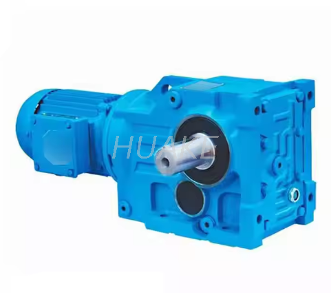
Furthermore, some applications require the smooth operation of curved teeth without the severe inward axial thrust generated by steep spiral angles. Enter the Zerol design. These gears have curved teeth but maintain a zero-degree spiral angle. They essentially bridge the mechanical gap between straight and spiral designs.
Since they do not produce excessive additional thrust forces, engineers can use them as direct drop-in replacements for straight gears. You do not need to upgrade the supporting bearings or redesign the housing. They offer quieter operation than straight teeth but cannot quite match the extreme torque density of full spiral configurations.
In contrast to the previous designs, hypoid gears operate on non-intersecting axes. The pinion sits either above or below the centerline of the ring gear. This offset geometry creates a distinct sliding action along the teeth during rotation.
Why is this offset valuable? It allows for larger pinion diameters. A larger pinion significantly increases the contact ratio and overall mechanical strength. You will frequently see these in automotive differentials and heavy robotics. The sliding friction does generate more heat. Consequently, these systems require specialized extreme-pressure lubricants to prevent premature surface wear.
Selecting the right profile requires balancing multiple mechanical factors. Use the following baseline metrics to guide your initial design phase.
| Gear Type | Speed Capability | Noise Level | Load Capacity | Manufacturing Cost |
|---|---|---|---|---|
| Straight | Low | High | Moderate | Low |
| Spiral | High | Low | High | High |
| Zerol | Moderate | Moderate | Moderate | Moderate |
| Hypoid | High | Low | Very High | Very High |
The global industrial landscape is rapidly shifting toward automation and strict energy efficiency standards. Recent market analyses highlight a surging demand for miniaturized yet high-torque transmission systems. Factories are actively upgrading legacy equipment with smart motors and precision drives. This macro trend forces gear manufacturers to push the boundaries of metallurgy and multi-axis CNC machining.
The modern Helical Bevel Gearbox must now deliver higher power density in a significantly smaller footprint. It needs to fit into tight robotic joints and compact automated guided vehicles. Sustainability initiatives are also driving the massive phase-out of low-efficiency worm gears in favor of these advanced right-angle solutions. Engineers are no longer just buying gears; they are investing in long-term energy savings.
Choosing the right component goes far beyond matching shaft diameters. You must evaluate the entire dynamic system to prevent catastrophic field failures.
First, assess your input speed. If your motor runs above 1000 RPM, eliminate straight teeth immediately. The resulting noise and vibration will destroy adjacent components. Spiral designs are mandatory here.
Second, calculate your spatial constraints. If your design allows for intersecting axes, standard spiral profiles are optimal. If your shafts must pass each other without intersecting due to space limitations, hypoid is your only viable option.
Third, analyze the thrust loads. High-torque spiral drives generate massive axial forces. Your housing and bearings must be robust enough to handle this directional stress. For heavy-duty industrial applications requiring a 90-degree turn, integrating a complete Right Angle Gear Reducer often saves months of engineering time compared to designing a custom gearset and bearing housing from scratch.
Well-machined spiral and straight configurations typically operate at 95 to 98 percent efficiency. Hypoid designs drop slightly to around 90 to 95 percent due to the inherent sliding friction between the offset teeth. Proper lubrication is mandatory to maintain these efficiency ratings.
The manufacturing process requires specialized multi-axis CNC gear generators. Cutting complex curved geometry with precise contact patches demands tighter machining tolerances and significantly longer cycle times compared to simple straight cuts. The investment pays off in lifespan and noise reduction.
Yes. Most standard industrial designs are bidirectional. However, the contact pattern on the coast side of the tooth may differ slightly from the drive side. You must ensure your lubrication system functions effectively in both rotational directions to prevent dry starts.
Selecting the precise power transmission setup dictates the lifespan, noise level, and efficiency of your entire machine. Straight teeth work perfectly fine for simple manual mechanisms. Yet, modern industrial automation heavily relies on the smooth, high-torque capabilities of curved tooth profiles to maintain 24/7 production cycles.
When your project demands uncompromising reliability, you need proven industrial solutions. Explore the comprehensive range of power transmission components at Huake Gearbox. Whether you require a standalone reducer for a custom build or a fully integrated Bevel Gear Motor, their engineering team provides the exact specifications to keep your operations running smoothly and profitably.


