
- All
- Product Name
- Product Keyword
- Product Model
- Product Summary
- Product Description
- Multi Field Search


Views: 0 Author: Site Editor Publish Time: 2026-10-13 Origin: Site


Power transmission dictates production efficiency on the factory floor. Choosing the wrong speed reducer leads to unexpected downtime and destroyed profit margins. Plant managers and maintenance engineers constantly face the challenge of matching mechanical drives to specific load requirements. Understanding the fundamental architectural differences in drive systems is the first step toward building a reliable production line.
Specifically, heavy machinery relies heavily on three primary mechanical architectures. Each design solves a unique kinetic problem.
Engineers categorize drive systems based on gear tooth geometry and shaft alignment. The mechanical layout determines load capacity, speed reduction ratios, and spatial footprint.
Parallel Shaft Configurations
This design dominates applications requiring continuous high-speed operation. The teeth are cut at an angle to the face of the gear. This angled cut allows the teeth to engage gradually. Smooth engagement reduces vibration and minimizes noise levels even at high rotational speeds. A well-machined Helical Gearbox offers exceptional power efficiency. Energy loss is typically less than two percent per stage. These units are the backbone of conveyor networks and large-scale agitators.
Right-Angle Power Routing
Plant layouts often demand a change in power direction. Intersecting shafts require a different approach. Spiral bevel designs excel here. The curved teeth provide a larger contact area compared to straight-cut alternatives. This increased surface area translates to massive torque handling capabilities. For instance, advanced Bevel Gearbox configurations can effortlessly drive heavy crushers and mining elevators. They redirect kinetic energy by ninety degrees without sacrificing structural integrity.
High-Density Coaxial Systems
Space is a premium in many modern machine designs. When engineers need maximum torque in a minimal footprint, they turn to epicyclic designs. A central sun gear drives multiple surrounding planet gears. An outer ring gear contains the entire assembly. This arrangement distributes the mechanical load across multiple contact points simultaneously. A Planetary Gearbox delivers unparalleled torque density. They are essential for heavy-duty robotics, tunnel boring machines, and extreme shock-load environments.
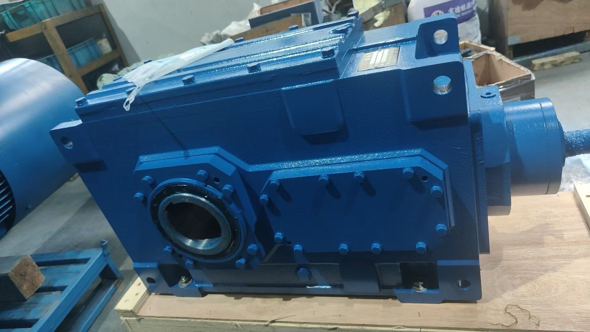
Furthermore, theoretical knowledge must translate into practical application. Specifying an Industrial Gearbox requires matching operational data to equipment capabilities. Consider the Huake HB Series as a benchmark for heavy-duty applications. These units offer torque ranges up to 470,000 Nm. The gear ratios span from 1.25 to 450. Such broad parameters allow engineers to fine-tune the drive system for exact application needs.
The following comparison matrix outlines the critical selection criteria for plant engineers.
| Drive Architecture | Primary Advantage | Ideal Application Environment | Efficiency Rating |
|---|---|---|---|
| Helical Parallel Shaft | High-speed continuous operation | Conveyors, Extruders, Pumps | Very High |
| Spiral Bevel Right-Angle | Directional power routing | Crushers, Mixers, Hoists | High |
| Epicyclic Planetary | Extreme torque in compact spaces | Tunneling, Heavy Robotics | Medium to High |
In contrast to generic catalogs, real-world selection demands a focus on thermal capacity and service factors. A unit might handle the mechanical torque but fail due to overheating in a poorly ventilated facility. Always calculate the service factor based on actual shock loads and daily operating hours.
The mechanical drive sector is undergoing a massive digital transformation. Modern industrial operations can no longer tolerate run-to-failure maintenance strategies. Recent industry analyses highlight a rapid integration of condition monitoring sensors directly into the drive housings.
Engineers are now deploying systems that continuously measure vibration signatures, oil temperature, and acoustic emissions. This real-time data feeds into predictive algorithms. Plant operators receive alerts weeks before a catastrophic bearing failure occurs. Consequently, the focus has shifted from pure mechanical robustness to intelligent asset management. Energy efficiency regulations are also forcing manufacturers to tighten machining tolerances and develop advanced synthetic lubrication protocols.
Mechanical reliability directly impacts the bottom line. Frequent gear replacements drain maintenance budgets and halt production schedules. Investing in precisely engineered drive solutions lowers the total cost of ownership. High-quality casing materials prevent oil leaks and resist environmental corrosion. Precision-ground gear teeth reduce friction. Lower friction means less heat generation and longer lubricant life.
Every plant manager must evaluate the hidden costs of cheap alternatives. A slight reduction in upfront capital expenditure often results in massive losses during unplanned outages.
The decision relies entirely on your spatial constraints and equipment layout. If the motor and the driven equipment can sit in a straight line, a parallel shaft configuration is usually more cost-effective and slightly more efficient. If your floor plan requires the motor to sit perpendicular to the driven shaft to save space, a right-angle design is mandatory.
Contaminated lubrication and improper alignment are the leading culprits. Water or particulate matter in the oil degrades the protective film between bearing rollers. Additionally, if the motor shaft and the input shaft are not perfectly aligned, it creates excessive radial loads. These unintended forces destroy bearings long before their rated lifespan.
Yes. Epicyclic designs are uniquely suited for this dual requirement. The load distribution across multiple planet gears absorbs sudden kinetic shocks effectively. Meanwhile, the tight machining tolerances inherent in these designs minimize backlash. This makes them ideal for applications demanding exact rotational positioning under heavy stress.
Selecting the correct power transmission architecture requires rigorous analysis of load dynamics, spatial limitations, and environmental conditions. Whether your facility demands the high-speed efficiency of parallel shafts, the directional flexibility of right-angle units, or the raw power of planetary systems, precision engineering is non-negotiable.
Do not compromise your production efficiency with mismatched equipment. Evaluate your specific torque requirements and operational demands carefully. For plant managers and engineers seeking robust, field-proven solutions, explore the comprehensive technical specifications of the Huake HB Series. Visit Huake Gearbox to find the exact mechanical drive engineered to optimize your industrial applications.


