
- All
- Product Name
- Product Keyword
- Product Model
- Product Summary
- Product Description
- Multi Field Search


How do you balance massive torque with precise low-speed control? Automated machinery demands exact mechanical pacing, and an integrated drive unit solves this very industrial headache. In this guide, we break down how to specify the right equipment for your exact footprint and load. We will explore core mechanics, varied configurations, and real-world selection tactics designed for plant engineers and technical buyers.
Power transmission is not just about moving parts; it is about controlled, reliable force. In industrial engineering, power must be carefully managed to ensure machinery operates efficiently and safely. This integrated unit seamlessly binds two mechanical worlds into one compact footprint.
Standard setups pair a prime mover with a torque multiplier. Back in the day, engineers bolted separate standalone motors and discrete gearboxes together via coupling mechanisms. While modular setups still exist in massive mining operations, integrated units dominate modern factory floors.
By casting the motor and gearbox housing together, manufacturers eliminate external couplings. This design choice practically wipes out shaft misalignment, which is a notorious culprit behind blown bearings. Furthermore, this cohesive design shrinks the installation footprint and saves precious assembly time on the production line.
The power source dictates performance. The choice between Alternating Current and Direct Current depends heavily on your operational environment and control demands.
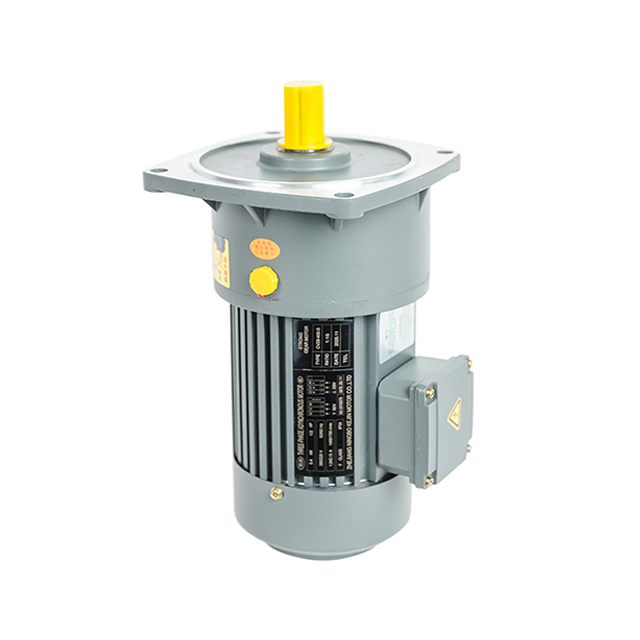
To spec a drive system correctly, you have to understand the physics of mechanical conversion. The gearbox essentially acts as a mechanical mediator between high speed and heavy loads.
A standard electric motor spins wildly fast, often between 1,500 and 3,600 revolutions per minute, but it lacks the muscle to move dead weight. Hook a raw high-speed motor directly to an industrial dough mixer, and it will just stall, hum, and eventually smoke.
The gearhead steps in to provide mechanical advantage. As kinetic energy travels through interlocking gear stages, the speed drops. Thanks to the laws of physics, as rotational speed decreases, torque surges proportionally, minus minor frictional heat losses. Consequently, a relatively small motor can confidently move massive loads at a highly controllable pace.
This relationship is expressed as a gear ratio. You determine this metric by dividing the driven gear teeth by the driving gear teeth.
If a ratio is stated as 50:1, the motor shaft must spin 50 times to rotate the output shaft exactly once. Pair a 1,500 revolutions per minute AC motor with a 50:1 reducer, and you get a highly controllable 30 revolutions per minute output. Simultaneously, the base torque of the motor is multiplied by roughly 50, providing immense pulling power.
| Motor Input Speed | Gear Ratio | Theoretical Output Speed | Torque Multiplier |
|---|---|---|---|
| 1500 | 10:1 | 150 | ~10x |
| 1500 | 30:1 | 50 | ~30x |
| 1500 | 50:1 | 30 | ~50x |
| 1500 | 100:1 | 15 | ~100x |
The internal geometry of the gears determines load capacity, efficiency, and physical shape. Selecting the correct mechanical layout is a critical decision that impacts the entire lifecycle of your machine.
When assessing standard inline builds, a Helical Gear Motor stands out as an incredibly efficient industrial reducer. The angled teeth engage gradually, allowing multiple teeth to share the load simultaneously. This translates to whisper-quiet operation and extreme efficiency, often hitting 98 percent per gear stage. They are the go-to choice for high-capacity, continuous operations like plastic extruders and heavy material handling.
If your machine frame demands a strict 90-degree power turn, a Bevel Gear Motor is the standard solution. Utilizing cone-shaped gears, usually spiral bevels for smoother meshing, they transmit heavy torque around corners without breaking a sweat. In addition, this right-angle geometry is a lifesaver in cramped plant layouts, letting engineers tuck the drive neatly alongside the conveyor frame.
On a tighter budget? A Worm Gear Motor also delivers a 90-degree turn but relies on a screw-shaft sliding against a toothed wheel. They run quietly and save money. More importantly, high-ratio worm drives are naturally self-locking. If power fails on a heavy vertical lift, the gear geometry prevents the load from back-driving and crashing down. However, the sliding friction does eat into overall mechanical efficiency, which must be accounted for during the design phase.
When axial space is virtually non-existent, a Parallel Shaft Gear Motor saves the day. By arranging helical or spur gears so the input and output shafts run side-by-side, manufacturers create an ultra-slim profile. They are perfect for tightly packed agitators or narrow sorting belts where a long, protruding inline motor would block foot traffic.
A common debate in machine design is whether to use a direct drive motor or a mechanically reduced unit. Both have empirical advantages depending on your specific load targets.
Direct drives bolt straight to the load. No gears mean zero mechanical backlash, no oil leaks, and zero gear wear. They dominate high-speed, high-precision servo applications. Conversely, to generate massive torque at low speeds, a direct drive motor must be physically gigantic. This bulk makes them exceptionally heavy and cost-prohibitive for standard heavy lifting scenarios.
Integrated reducers provide unmatched torque density. A compact, budget-friendly motor bolted to a gearbox matches the low-speed muscle of a direct drive unit triple its size. While gears do require routine lubrication and eventually wear out, mechanical reduction remains the most pragmatic, economical reality for heavy industry.
These power transmission solutions are the driving force behind both traditional manufacturing and cutting-edge automation.
In standard manufacturing environments, these units are the heartbeat of the factory floor. They drive conveyor belt systems to ensure materials move at a steady pace regardless of weight. They provide precise indexing in packaging machinery, and they deliver the immense rotational force required for rock crushers and industrial mixers.
Looking at the broader industrial landscape, expectations for power transmission are rapidly evolving. Driven by strict global energy mandates and the rise of smart manufacturing, there is a massive industry-wide shift toward predictive maintenance and ultra-high-efficiency systems. Today's engineers are actively phasing out legacy, energy-hungry drives in favor of smart Industrial Gear Motor units embedded with vibration and thermal sensors. These intelligent systems flag bearing wear or oil degradation long before a catastrophic failure stops the assembly line. Furthermore, the booming renewable energy sector is pushing demand for highly weather-resistant drives to operate solar panel trackers, while the logistics boom requires ultra-compact, high-efficiency DC units for automated warehouse robotics.
Specifying the correct equipment requires precise mathematical calculations and a thorough understanding of the operating environment. Guesswork leads to premature mechanical failure or wasted capital on oversized units.
Do not guess your load requirements. Calculate the exact continuous running torque and the peak starting torque, which spikes significantly to overcome static inertia. Crucially, factor in the Service Factor. If your pump runs continuously or your crusher eats heavy shock loads, you must multiply your base torque requirement by a service factor of 1.5 or 2.0. This ensures the internal gear teeth will not shear off during a sudden jam.
Match the electrical characteristics to your facility grid. Heavy plants use three-phase AC power, such as 230V or 480V, for smooth, continuous running. Mobile machinery and remote equipment rely on 12V, 24V, or 48V DC battery banks.
The room dictates the build. A dusty sawmill needs high Ingress Protection sealing, like IP65. A meat processing plant doing daily high-pressure chemical washdowns demands IP69K stainless steel units. Additionally, extreme ambient temperatures require specialized synthetic oils so the internal lubrication does not turn to sludge or water.
Geometry matters. Choose between foot-mounted units bolted to the floor, flange-mounted units bolted straight to the machine, or hollow-shaft setups that slide directly onto the driven axle. Always verify the gearbox bearings can handle the radial load if you are attaching sprockets or pulleys to the output shaft.
Paper specs mean nothing if the manufacturing is sloppy. Source from facilities that use precision CNC gear hobbing to minimize backlash and noise. For tough applications, off-the-shelf products will not cut it. Work with specialists who can tweak shaft dimensions, seals, and gear ratios to your exact reality.
An optimized drive system controls speed and multiplies torque, serving as the reliable muscle behind your automated processes. Whether you need the high efficiency of a helical unit or the space-saving geometry of a right-angle drive, sizing it correctly prevents costly downtime. Ready to upgrade your machinery performance? Evaluate your footprint, calculate your exact load requirements, and explore reliable, precision-engineered solutions at https://www.huakegearbox.com to find the perfect power transmission match for your facility.
A gearbox is just the mechanical housing with gears; it requires you to supply and carefully align a separate motor. An integrated unit combines both the motor and the gearbox into a single, factory-aligned piece, saving space and eliminating coupling alignment headaches.
Yes, the vast majority are fully reversible. Swap two phases on a three-phase AC unit, or flip the polarity on a DC unit. However, beware of high-ratio worm drives. They are often mechanically self-locking and will not back-drive when power is cut.
With proper sizing and a clean environment, expect 10,000 to 30,000 operating hours. Keep the cooling fins clean and strictly adhere to the manufacturer oil change schedule to hit that upper limit.
There are two primary ways. You can swap to a gearbox with a higher numerical ratio, which increases torque but drops your output speed. Alternatively, you can bolt on a higher-horsepower motor, provided you verify the existing gear teeth are rated to handle the extra input force without shearing.
Overheating typically stems from overloading the equipment beyond its rated torque, operating in an environment with poor ventilation, or running with degraded lubrication. Frequent stop-start cycles without adequate cooling time can also cause internal motor windings to exceed their thermal limits.
Brushed motors are cost-effective and simple to wire, making them great for basic, intermittent-duty applications. Brushless DC motors require an electronic controller but offer significantly longer lifespans, higher efficiency, and zero brush maintenance, making them the superior choice for continuous, high-precision automation.


