
- All
- Product Name
- Product Keyword
- Product Model
- Product Summary
- Product Description
- Multi Field Search


Views: 0 Author: Site Editor Publish Time: 2026-10-12 Origin: Site


Executing a reducer ratio calculation requires absolute precision. The specific type of drive you select fundamentally alters the final mathematical output. Engineers frequently rely on the helical gear design for heavy-duty industrial applications due to its distinct mechanical advantages. Recent industry analyses indicate a massive shift toward energy-efficient automation across global manufacturing sectors. Facilities are currently striving to meet stringent carbon emission standards while simultaneously reducing operating expenses. Consequently, the demand for precise power transmission sizing has skyrocketed. Selecting highly efficient components is no longer optional. It has become a strict engineering mandate.
Unlike standard spur gears that feature straight teeth, a Helical Gear Reducer utilizes teeth cut at a precise angle to the face of the gear. This angled geometry allows the teeth to engage gradually rather than slamming together all at once. This gradual meshing yields a higher contact ratio. It significantly dampens operational noise, minimizes vibration, and permits the transmission of substantial shock loads without shearing the gear teeth.
The most critical factor impacting your mathematical models is mechanical efficiency. When adapting an electric motor to achieve a targeted Output Speed, a fraction of the input power is inevitably lost as heat due to internal friction. Ignoring this thermal loss leads to undersized equipment and eventual system failure.
Different Speed Reducer designs possess vastly varying efficiency ratings. Worm gearboxes are notorious for high friction losses. They sometimes operate at only 50 to 70 percent efficiency depending on the specific ratio and sliding velocity. In stark contrast, helical gears are highly efficient. A standard helical unit typically operates at a remarkable efficiency rate of 95 to 98 percent per gear stage.
To ensure your machine does not stall under a heavy load, you must insert this efficiency multiplier directly into your final torque calculation.
The Practical Engineering Formula:
Actual Output Torque = Input Torque × Gear Ratio × Gearbox Efficiency
Field Calculation Example:
Assume you have calculated a required ratio of 20:1. Your electric motor provides 100 pound-inches of input torque.
If your conveying machinery requires exactly 2,000 pound-inches to overcome static friction and move the payload, failing to account for that 5 percent efficiency loss is disastrous. Your motor will stall, draw locked-rotor current, overheat, and potentially suffer catastrophic winding failure.
Below is a reference table showcasing typical efficiency ratings across different gearbox configurations. This data highlights exactly why helical designs are preferred for high-torque accuracy in modern automation:
| Gearbox Type | Typical Efficiency Range Per Stage | Best Application Use Case |
|---|---|---|
| Helical Gear | 95% - 98% | High torque, continuous duty, low noise. |
| Spur Gear | 94% - 97% | Low speed, moderate load, cost-sensitive projects. |
| Bevel Gear | 95% - 98% | Right-angle power transmission with minimal power loss. |
| Worm Gear | 50% - 90% Ratio dependent | High reduction in a compact space, self-locking requirements. |
Even seasoned engineers can make critical errors during the specification phase. Reviewing common mistakes discussed in industrial automation circles reveals three primary pitfalls that consistently lead to mechanical failure. Avoiding these oversights requires bridging the gap between theoretical mathematics and harsh real-world applications.
As demonstrated in the previous section, assuming total power transfer is a rookie mistake. Theoretical math is flawless on paper. However, it fails to account for bearing friction, lubricant drag, or gear mesh resistance. Imagine a plant manager ordering a drive for a heavy-duty mining conveyor. If they rely solely on raw math without accounting for mechanical drag, they will purchase an undersized motor lacking sufficient starting torque. Always use the manufacturer stated efficiency rating when finalizing your Gear Ratio calculations.
A surprising number of mechanical failures occur simply because the ratio is flipped on the procurement sheet. A ratio of 4:1 indicates a speed reduction. This means the motor turns four times to achieve one single rotation of the output shaft. Conversely, a ratio of 1:4 indicates an overdrive or speed multiplication. If a maintenance technician accidentally installs a 1:4 gearbox when a 4:1 reduction is required, the output speed will be dangerously fast. Simultaneously, the available torque will be divided by four, resulting in immediate motor stalling. Always ensure the driving input gear and driven output gear are correctly positioned in your mathematical formula.
Standard mathematical formulas assume a perfectly uniform load running in ideal, climate-controlled conditions. Real-world industrial environments are rarely ideal. The Service Factor is an essential multiplier applied to your calculated baseline torque to account for operational stress and fatigue.
If your machinery experiences heavy shock loads, frequent stop-start cycles, or runs continuously all day, you must increase this buffer. Failing to apply the correct service factor will cause premature pitting on the gear teeth and rapid bearing degradation. This inevitably leads to expensive unplanned downtime.
| Load Type | 3 to 10 Hours Daily | 10 to 24 Hours Daily | Example Industrial Applications |
|---|---|---|---|
| Uniform Load | 1.00 | 1.25 | Centrifugal pumps, light assembly conveyors. |
| Moderate Shock | 1.25 | 1.50 | Industrial mixers, heavy-duty packaging lines, cranes. |
| Heavy Shock | 1.75 | 2.00 | Rock crushers, plastic extruders, metal stamping presses. |
Understanding the mathematics represents only the initial phase of the procurement process. The ultimate objective of your calculations is to procure a physical component that will reliably perform in your manufacturing facility. Moving from theoretical equations to purchasing requires a highly structured evaluation of the hardware.
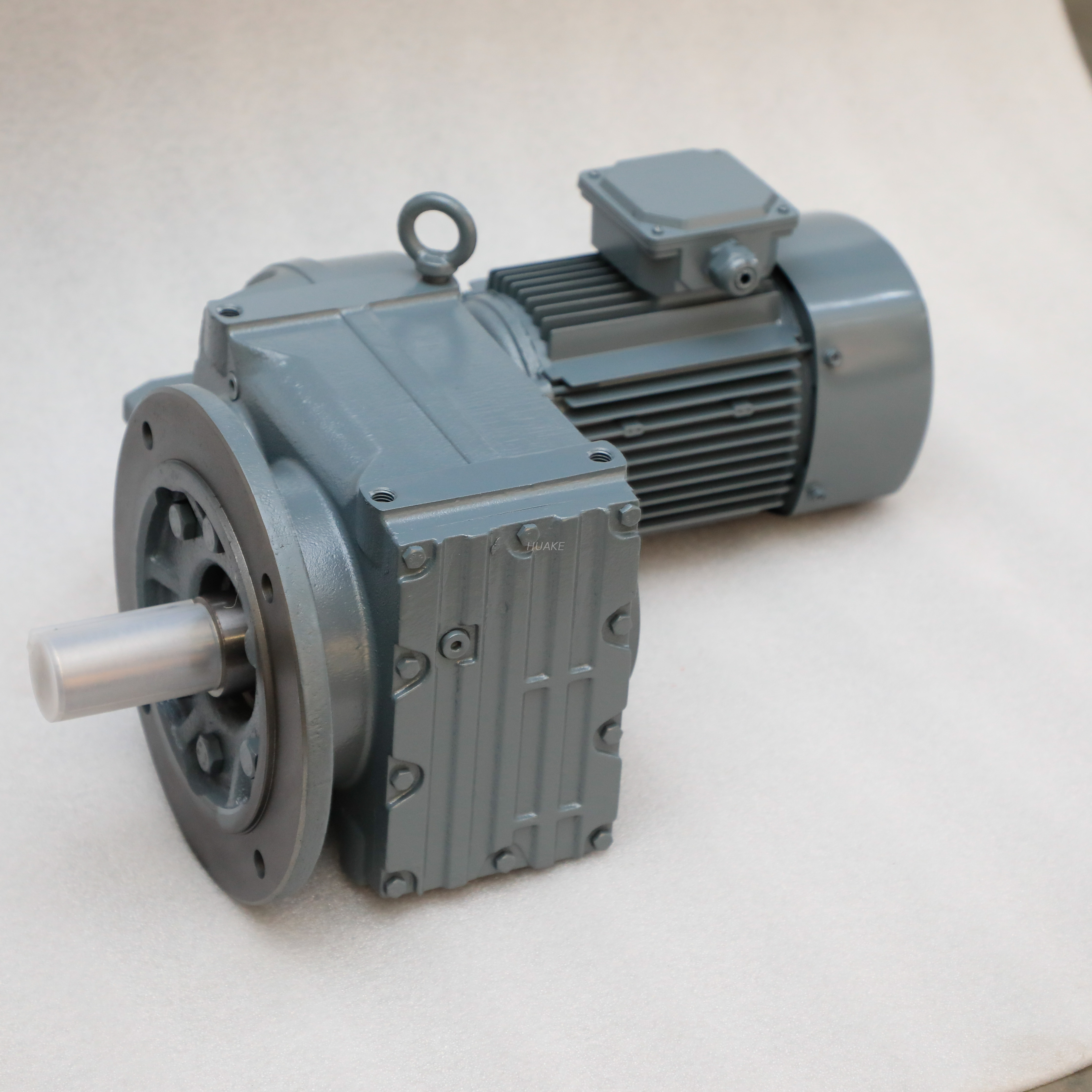
When you are ready to specify an Industrial Gearbox, utilize the following comprehensive criteria to ensure all engineering variables are thoroughly covered. For instance, F-Series parallel shaft helical gear reducers are specifically engineered for heavy-duty conveying systems. They provide exceptional torque density and can maintain a mechanical efficiency of up to 98 percent, making them ideal for rigorous applications.
Industrial power transmission is highly complex. Procurement managers and mechanical engineers should consult directly with manufacturers. Providing a factory engineer with your baseline calculations allows them to verify your math. They can then recommend a unit with the exact thermal and mechanical capacity required for your specific application.
Accurate calculations prevent costly machine failures and operational bottlenecks. You must measure the target speed carefully while always accounting for internal efficiency ratings and environmental service factors. Identifying the correct torque ensures smooth startup operations and significantly extends the lifespan of your mechanical assets. If you are upgrading your facility or designing a new heavy-duty system, explore the robust transmission solutions available at Huake Gearbox. Consulting engineering experts before making final purchases lays the groundwork for long-term project success and maximized industrial productivity.
A gear reduction occurs when the driving input gear from the motor is physically smaller and has fewer teeth than the driven output gear. Mathematically, it is represented by a ratio greater than one to one. For example, a ratio of 5:1 means the input shaft must complete five full rotations to turn the output shaft exactly one time. This mechanical arrangement decreases the final rotational speed while proportionally increasing the available turning force.
Yes, you can accurately determine the ratio without opening the cast-iron housing to count individual gear teeth. If you know the exact input RPM of your electric motor and can measure the final output RPM of the gearbox shaft using a handheld tachometer, you simply divide the input speed by the output speed. For instance, if a motor spinning at 1800 RPM is connected to a reducer, and the final shaft spins at 60 RPM, the ratio is exactly 30:1.
The concept of a good ratio is highly subjective and depends entirely on the specific mechanical requirements of the load being moved. Higher gear ratios, such as 50:1, 100:1, or even higher in multi-stage units, produce significantly higher torque because they reduce the rotational speed more drastically. Heavy industrial equipment like rock crushers or large lifting hoists typically require these high numerical ratios to generate sufficient rotational force without stalling the electric motor.
No, a speed reducer cannot generate or increase horsepower. Power transmission devices only trade rotational speed for torque. According to the fundamental laws of physics, power in equals power out, minus friction. Because of the mechanical friction generated by the meshing of internal gears and bearings, the actual output horsepower will always be slightly lower than the input horsepower provided by the motor.
You must multiply the input torque of the motor by the gear ratio, and then multiply that result by the mechanical efficiency rating of the gearbox. This three-step formula ensures you account for internal friction losses. Neglecting the efficiency variable will result in an undersized motor that stalls under peak industrial loads.
Selecting an incorrect ratio leads to immediate mechanical incompatibility. If the ratio is too low, the output shaft will spin too fast, but it will lack the rotational force needed to move the heavy load. The motor will draw excessive current and overheat. Conversely, a ratio that is too high will provide excessive force but operate at a sluggish speed, severely bottlenecking your production line throughput.


