
- All
- Product Name
- Product Keyword
- Product Model
- Product Summary
- Product Description
- Multi Field Search


A gear reducer is a mechanical transmission device used to reduce the rotational speed of a motor or other power source while increasing the torque available at the output shaft. It is commonly installed between a motor and driven equipment such as a conveyor, mixer, pump, lifting mechanism, production machine, or automated system. Industrial motors often operate at speeds that are much higher than the speed required by the actual machine, so a gear reducer converts that high-speed input into a more suitable output speed. The reduction is created by gears with different numbers of teeth or different pitch diameters operating together inside a gearbox housing. As output speed decreases, available output torque generally increases according to the transmission ratio and mechanical efficiency of the reducer. A gear reducer does not create additional power because some energy is always lost through friction, gear meshing, bearings, seals, and lubrication. Its purpose is to transform the available motor power into the combination of speed and torque required by the driven machine. Different internal gear arrangements also allow a reducer to change shaft direction, fit into limited installation spaces, support high loads, or provide precise motion control. Helical, bevel, planetary, worm, cycloidal, and cylindrical gear designs are therefore used for different industrial requirements. Selecting the wrong reducer can result in insufficient torque, excessive heat, premature bearing wear, poor efficiency, or shortened service life. HUAKE provides multiple industrial reducer designs for applications ranging from general machinery and conveying systems to automation and precision robotic transmission. Understanding how a gear reducer works makes it easier to select the correct ratio, torque capacity, gearbox structure, mounting position, and motor combination for a new machine.
A gear reducer works by transmitting rotational motion through one or more gear stages between an input shaft and an output shaft. The input gear is usually connected directly or indirectly to an electric motor, engine, servo motor, or another source of mechanical power. When a smaller input gear drives a larger output gear, the larger gear rotates more slowly than the input gear. This reduction in rotational speed is represented by the gear ratio. For example, an ideal 10:1 reduction means that the input shaft turns approximately ten times for every one revolution of the output shaft. At the same time, the output torque increases because the reducer trades rotational speed for mechanical turning force. Real gearboxes are not perfectly efficient, so actual output torque is lower than the theoretical torque calculated from ratio alone. Gear geometry, bearing friction, lubricant behavior, seal resistance, operating temperature, and load conditions all affect efficiency. Multi-stage reducers use several gear pairs when one gear stage cannot provide the required total ratio or packaging arrangement. Different gear arrangements can also change the direction of the output shaft, allowing inline, parallel-shaft, or right-angle transmission layouts. The housing supports shafts, bearings, gears, seals, and lubricant while maintaining the alignment required for stable gear meshing. A properly selected reducer therefore acts as both a speed-changing device and a torque-transmission system between the motor and the working machine.
| Parameter | Basic Meaning |
|---|---|
| Input Speed | Motor or driving shaft speed |
| Output Speed | Speed delivered to the machine |
| Gear Ratio | Input speed ÷ output speed |
| Input Torque | Torque entering the reducer |
| Output Torque | Increased torque available after reduction |
| Efficiency | Percentage of input power transmitted through the gearbox |
| Service Factor | Allowance for load severity and operating conditions |
| Backlash | Clearance between mating gear teeth |
Gear ratio is one of the first specifications engineers consider because it determines how much the reducer changes the input speed. If a motor operates at 1,500 rpm and the required machine speed is approximately 50 rpm, the theoretical reduction ratio is about 30:1. This does not automatically mean that any 30:1 gearbox will work because torque, efficiency, duty cycle, mounting arrangement, and load characteristics still need to be checked. A higher ratio generally produces a lower output speed and a greater theoretical multiplication of torque. The actual output torque can be estimated from input torque multiplied by the gear ratio and the efficiency of the transmission. Efficiency becomes especially important when several reduction stages are used because losses accumulate through each stage. Helical and bevel gearing can provide relatively efficient mechanical transmission for many continuous-duty applications. Worm gearing can provide large reductions in a compact right-angle arrangement, but its sliding contact can produce different efficiency and thermal characteristics depending on ratio and operating conditions. Planetary and cycloidal designs can provide high torque density and compact transmission when space and load requirements are demanding. Engineers should also consider the available motor speed because a variable-frequency drive or servo motor can change the operating speed range seen by the reducer. Maximum input speed must remain within the gearbox specification even when the motor is operated above its nominal frequency. Selecting the ratio therefore requires matching both the normal operating point and the complete expected speed range of the machine.
| Example Input | Value |
|---|---|
| Motor Speed | 1,500 rpm |
| Required Output Speed | 50 rpm |
| Theoretical Ratio | 30:1 |
| Input Torque | 20 N·m |
| Ideal Torque at 30:1 | 600 N·m |
| Actual Output Torque | Lower than ideal after efficiency losses |
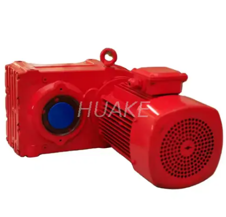
Gear reducers are classified primarily by their internal gearing and shaft arrangement because each design creates a different balance of efficiency, torque density, reduction ratio, precision, noise, size, and cost. Helical reducers use angled teeth that enter engagement gradually, which supports smooth transmission and makes them common in conveyors, processing machinery, material handling, and other continuous industrial drives. Parallel-shaft helical reducers are especially useful when the input and output shafts need to remain parallel while the machine requires relatively high torque in a compact layout. HUAKE's F Series Parallel Shaft Helical Gearmotor covers ratios from 3.81 to 281.71 on the current product page and is designed for industrial power-transmission applications. Bevel reducers use intersecting gear geometry to change transmission direction and are widely used where the output needs to turn through approximately 90 degrees. The KA47 Spiral Bevel Gear Reducer is a compact right-angle example intended for applications such as conveyors, packaging equipment, mixers, and automation. Worm reducers use a worm and worm wheel to achieve substantial speed reduction in a compact right-angle configuration, making them common where space and cost are important. Planetary reducers distribute load across several planet gears and are frequently selected where compact size, torque density, and precise transmission are important. Cycloidal reducers use cycloidal motion and multiple contact points to provide high reduction ratios, high load capacity, and strong resistance to impact loads in selected applications. Cylindrical gear reducers are another established option for heavy industrial machinery where robust transmission and high load capability are required. The correct reducer type should therefore be selected from the machine's torque, ratio, precision, shaft arrangement, space, efficiency, duty, and operating environment rather than from one general claim that a particular gear technology is always best.
| Reducer Type | Typical Strength | Common Application Direction |
|---|---|---|
| Helical | Smooth, efficient transmission | Conveyors, industrial machinery |
| Parallel-Shaft Helical | High torque in compact parallel layout | Material handling, process equipment |
| Bevel / Helical-Bevel | Efficient right-angle transmission | Packaging, automation, conveyors |
| Worm | Compact high-ratio right-angle drive | General machinery, positioning |
| Planetary | High torque density and compact size | Automation, servo systems |
| Cycloidal | High ratio and strong load capacity | Robotics, precision machinery |
| Cylindrical | Robust heavy-duty transmission | Mining, metallurgy, industrial equipment |
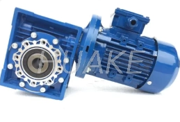
A worm gear reducer uses a screw-like worm that meshes with a worm wheel, producing a right-angle output and allowing relatively large speed reductions within a compact housing. The sliding action between the worm and wheel is different from the predominantly rolling contact found in many helical, bevel, and planetary gear arrangements. This difference influences efficiency, heat generation, lubrication requirements, and operating behavior. Worm gearboxes are frequently used where compact dimensions, simple right-angle transmission, stable low-speed operation, and economical construction are priorities. They can also provide very high ratios through single or combined stages without requiring a long inline gearbox. HUAKE's Compact Aluminum NMRV Worm Gearbox includes RV30 through RV150 models and offers single-stage ratios from 1:7.5 to 1:100 according to its current product specifications. Double-stage NMRV configurations can achieve substantially higher ratios where very low output speeds are needed. An aluminum housing also helps reduce gearbox weight and improve heat dissipation for many light and medium industrial installations. However, worm reducers should not automatically be selected whenever a high ratio is required because efficiency and thermal performance can become important in continuously loaded applications. A helical or bevel reducer may provide a better lifecycle result when long operating hours and energy efficiency dominate the selection. Load direction and backdriving requirements should also be checked rather than assuming that every worm reducer is inherently self-locking. The best choice comes from comparing real operating torque, ratio, duty cycle, efficiency, temperature, installation space, and machine safety requirements.
The terms gear reducer and gearbox are often used interchangeably because both describe an enclosed gear transmission that changes speed and torque. In industrial terminology, “gear reducer” emphasizes the function of reducing speed, while “gearbox” is the broader mechanical term for the housing and gear train. A gearbox can technically be designed for speed reduction, speed increase, directional change, or another transmission purpose, although most industrial gearboxes used with electric motors function as reducers. A gear motor is different because it combines an electric motor and a gear reducer into one matched drive assembly. This integrated arrangement can simplify machine design because the motor flange, input connection, ratio, and output configuration are selected as one system. A separate gear reducer may be preferred when the machine already has a motor, when a special input device is required, or when the gearbox and motor need to be serviced independently. Gear motors are common on conveyors, packaging machines, mixers, material-handling systems, and automated production equipment because they reduce the number of field-installed components. Precision automation may instead combine a servo motor with a low-backlash planetary or cycloidal reducer so the transmission can support accurate positioning. Heavy industrial drives may use a standalone gearbox connected to a large motor through couplings or other power-transmission components. The terminology therefore matters less than understanding what components are included in the quotation and how they connect to the driven machine. Buyers should confirm whether a supplier is quoting only the reducer, a reducer with motor adapter, or a complete gear motor before comparing prices. Input flange, motor frame size, brake, encoder, coupling, output shaft, and mounting accessories can all change the final drive configuration. A technically correct comparison should therefore evaluate the complete transmission package rather than assuming that products with similar names include the same hardware.
| Term | Typical Meaning |
|---|---|
| Gear Reducer | Gear unit primarily used to reduce speed |
| Gearbox | General enclosed gear transmission |
| Gear Motor | Motor and reducer combined as one drive |
| Servo Gearbox | Precision reducer matched to servo control |
| Speed Reducer | Common alternative term for gear reducer |
Gear reducers are used wherever the available motor speed does not match the speed and torque required by the mechanical load. Conveyor systems use reducers to convert motor speed into controlled belt or chain speed while providing enough torque to start and move loaded material. Mixers and agitators require lower rotational speed and higher torque to move liquids, powders, or viscous materials effectively. Packaging machinery uses reducers to coordinate rollers, feeders, indexing systems, and other mechanical motions within a compact production line. Mining and bulk-material equipment often requires heavy-duty gear units because conveyors, crushers, feeders, and handling systems experience high loads and shock conditions. Food and beverage production also uses geared drives for conveying, filling, mixing, and processing equipment where stable speed is important. Chemical and environmental equipment may use reducers on mixers, scrapers, aerators, and handling systems that operate for long periods. Automation systems require more attention to backlash, inertia, acceleration, and positioning because movement accuracy can be as important as torque. Robotics pushes these requirements further because joint drives need high torque density and compact installation while maintaining repeatable motion. HUAKE's Precision RV Cycloidal Gear Reducer for Robot Joints is an example of a reducer designed around high-precision industrial transmission rather than general conveyor duty. Lifting and positioning equipment also uses reduction gearing because large mechanical loads need controlled low-speed movement. The wide range of applications explains why gear reducers cannot be selected from motor power alone, since two machines using the same motor can impose completely different torque, shock, precision, and operating requirements on the gearbox.
Selecting the right gear reducer starts with the required output speed and torque rather than with a preferred gearbox model. The engineer should first record the normal motor speed, motor power, peak motor speed, and available input torque. The required machine output speed then determines the approximate reduction ratio. Output torque should be calculated from the real mechanical load and should include acceleration, starting resistance, friction, process load, and other forces that the reducer must overcome. Peak torque deserves separate attention because a reducer that handles normal running torque may still fail when a conveyor starts fully loaded or a machine experiences a jam. Duty cycle is another important factor because continuous operation produces a different thermal load from intermittent operation. Service factor or application factor should be applied according to the manufacturer's selection method and the severity of the driven machine. Shaft arrangement should then be selected according to the mechanical layout, including inline, parallel-shaft, or right-angle output. Mounting position matters because lubrication behavior and accessory configuration may depend on gearbox orientation. Backlash requirements should be defined for positioning systems rather than applying precision gearbox specifications unnecessarily to simple continuous drives. Efficiency should be considered when energy consumption, temperature, or long operating hours make transmission losses economically important. Environmental conditions such as dust, moisture, corrosive exposure, ambient temperature, washdown, outdoor use, and explosive atmospheres may require different seals, coatings, lubrication, or motor protection. A complete reducer specification should therefore include ratio, torque, power, speed, service condition, mounting, shaft dimensions, motor interface, precision requirement, and installation environment before the final model is selected.
| Selection Item | Questions to Confirm |
|---|---|
| Motor Power | What kW or HP is available? |
| Input Speed | What is normal and maximum motor rpm? |
| Required Output Speed | What rpm does the machine need? |
| Gear Ratio | What reduction produces the required speed? |
| Output Torque | What continuous torque is required? |
| Peak Torque | What starting or shock load occurs? |
| Duty Cycle | Continuous, intermittent, or cyclic? |
| Shaft Arrangement | Inline, parallel, or right-angle? |
| Mounting | Foot, flange, shaft, hollow shaft? |
| Backlash | Is precision positioning required? |
| Environment | Dust, moisture, corrosion, heat, outdoor use? |
| Motor Interface | IEC motor, servo motor, direct coupling, other? |
Three specifications that are often overlooked during basic reducer selection are efficiency, backlash, and service factor. Efficiency determines how much input power is lost as heat instead of being transmitted to the driven machine. Small differences in efficiency can become important in continuously operating equipment because energy losses accumulate over thousands of operating hours. Higher gearbox losses also increase internal temperature, which can influence lubricant life, seals, and thermal capacity. Backlash describes the mechanical clearance between mating gear teeth and becomes important when the load repeatedly reverses direction or must stop at precise positions. A conveyor running continuously in one direction may tolerate more backlash than a robotic axis or indexing table. Precision reducers are therefore designed with much tighter motion characteristics than general industrial gearboxes. Service factor addresses another problem because a reducer rarely operates under a perfectly constant theoretical load. Starts, stops, shock loads, conveyor loading, machine jams, changes in operating hours, and environmental conditions can all increase the actual stress on the gearbox. A gearbox selected exactly at its nominal torque limit may therefore have insufficient margin for the real application. Oversizing without calculation is not ideal either because a much larger gearbox increases cost, weight, installation space, and rotating inertia. The correct approach is to use application-specific service factors and manufacturer selection data to establish sufficient mechanical and thermal capacity. Precision, efficiency, and load margin should therefore be matched to the actual machine instead of maximizing every specification.
One common mistake is choosing a reducer only from the motor power because motor kW does not describe the complete load seen by the gearbox. The same motor can drive a lightly loaded fan mechanism or a heavily loaded conveyor with very different starting torque. Another mistake is selecting only by ratio without checking the actual output torque and thermal capacity. Buyers also sometimes ignore peak loads and select a reducer that is adequate during normal production but undersized during acceleration or emergency conditions. Using a high-precision reducer where no positioning accuracy is required can increase cost without improving the machine's practical performance. The opposite error is using a general-purpose gearbox on a robotic or servo axis where backlash prevents accurate motion. Mounting position can also be missed, resulting in incorrect lubrication conditions or incompatible breather and oil-level arrangements. Shaft diameter and key dimensions should be checked before ordering because an otherwise correct gearbox can still be difficult to integrate mechanically. Environmental protection is another frequent oversight, especially where a reducer operates outdoors, in humid environments, around chemicals, or in dusty processing areas. Maintenance access should also be considered because oil changes, inspections, seals, and bearings may need attention during the equipment lifecycle. Engineers should avoid assuming that a larger ratio always gives more useful torque because the driven machine may exceed permissible output torque, shaft loads, or thermal limits before reaching the theoretical value. Comparing several reducer technologies against the same duty data is usually more reliable than choosing the type first and then trying to make the application fit it.
Gear reducer maintenance should follow the manufacturer's instructions because lubrication intervals, oil grade, bearing arrangements, seals, and inspection points differ between gearbox designs. The lubricant is especially important because it reduces friction, removes heat, protects gear surfaces, and helps prevent premature wear. Oil level should be checked according to the specified mounting position because the correct level can change when the same gearbox is installed vertically instead of horizontally. New equipment may require an initial inspection or lubricant change according to the manufacturer's schedule. Operating temperature should be monitored because an unexplained increase can indicate overload, insufficient lubrication, excessive friction, bearing damage, contamination, or ventilation problems. Abnormal noise should also be investigated rather than accepted as normal aging because damaged teeth, bearings, loose components, or misalignment can change the acoustic behavior of the gearbox. Oil leakage around shafts, plugs, joints, or seals should be corrected before lubricant loss becomes significant. External contamination should be removed where it can block cooling surfaces or enter the gearbox during service. Shaft alignment and connected equipment should be inspected because excessive external loads can shorten bearing and seal life even when the internal gears remain in good condition. Maintenance records are useful because temperature, vibration, oil condition, and noise trends can reveal gradual deterioration earlier than an unexpected failure. Gearboxes used in critical continuous-production equipment may justify condition monitoring or oil analysis when downtime is expensive. Correct selection and installation remain part of maintenance strategy because a properly sized reducer operating within its design conditions normally requires less corrective work than an undersized or misaligned unit.
HUAKE supplies several reducer technologies for industrial transmission rather than relying on one gearbox design for every application. The current product range includes helical, bevel, planetary, worm, cycloidal, and cylindrical gear reducers together with gear motors and worm gear screw jacks. This variety allows an engineer to begin with the machine requirement and then compare suitable transmission structures. Parallel-shaft helical reducers can be considered where efficient industrial power transmission and high torque are needed in a compact parallel arrangement. Spiral bevel reducers can support right-angle layouts where installation space and transmission efficiency are important. NMRV worm gearboxes provide another compact right-angle solution where a wide ratio range and flexible mounting are required. Precision RV cycloidal reducers address a different application class where robotics and precision automation require compact high-performance transmission. HUAKE's product information also covers motor compatibility, mounting configurations, ratios, output torque, and different model ranges that can support preliminary engineering selection. Buyers should still provide complete operating data because the correct reducer cannot be determined reliably from industry name or motor power alone. Ratio, torque, operating hours, shock loading, installation orientation, output shaft configuration, ambient conditions, and motor details should all be included in an RFQ. Non-standard requirements should be discussed before ordering so shaft dimensions, mounting, motor interfaces, or other mechanical details can be confirmed. Comparing the complete application data with several reducer architectures can help avoid unnecessary oversizing and improve the fit between the gearbox and driven machine. For industrial buyers, this application-based selection process is more useful than simply choosing the lowest-priced reducer with approximately the correct ratio.
A gear reducer is a mechanical transmission device that reduces rotational speed and increases usable output torque between a motor and driven machine. Its basic operating principle is straightforward, but correct selection requires much more than choosing a reduction ratio. Input speed, motor power, required output speed, continuous torque, peak torque, efficiency, service factor, mounting, and operating environment all influence the final gearbox choice. Helical reducers are widely used for smooth and efficient industrial power transmission. Bevel reducers provide compact directional changes for right-angle drives. Worm reducers provide practical high-ratio right-angle transmission for many general mechanical applications. Planetary reducers provide strong torque density in compact arrangements. Cycloidal reducers can support high ratios, load capacity, and precision applications such as robotic joints. Gear motors combine the motor and reducer into one drive package, while standalone reducers can be integrated with motors and other power sources separately. Precision and backlash requirements should be defined from the application rather than specified unnecessarily on every machine. Proper lubrication, alignment, load control, and inspection are also important for long gearbox life. HUAKE provides several industrial gear-reducer structures that can be evaluated according to the actual speed, torque, mounting, precision, and duty requirements of the machine. The most suitable reducer is therefore not simply the unit with the highest torque or largest ratio, but the gearbox that delivers the required output reliably within the complete mechanical system.
A gear reducer is used when the speed produced by a motor is higher than the speed required by the driven machine. The reducer decreases the rotational speed between the motor and output shaft. This speed reduction generally increases the available output torque. Conveyors commonly use reducers to achieve controlled belt speeds. Mixers use them to produce strong low-speed rotation. Packaging equipment uses reducers to coordinate mechanical movements. Lifting equipment can use reduction gearing to provide controlled motion under load. Automation systems use reducers where motor speed and machine speed need to be matched accurately. Precision systems may use low-backlash reducers for positioning. Heavy industrial machinery uses larger reducers to transmit substantial torque. The basic purpose is therefore to convert motor speed and torque into a form that is more suitable for the machine.
A gear reducer generally increases the torque available at its output as it reduces speed. In an ideal system, torque multiplication is related to the gear ratio. A 10:1 reducer theoretically provides approximately ten times the input torque before mechanical losses are considered. Real gearboxes have friction and other losses, so actual output torque is lower than the ideal calculation. Efficiency depends on the type of gearing and operating condition. The gearbox also has a maximum rated output torque that must not be exceeded. Peak torque needs to be checked separately from normal running torque. Starting and shock loads can create much higher torque than steady operation. Motor power limits the total mechanical power available to the system. A reducer therefore changes the relationship between speed and torque rather than creating new power. Proper sizing requires both calculated torque and manufacturer-rated capacity.
The two terms are often used interchangeably in industrial equipment. A gear reducer is a gearbox specifically used to reduce input speed. The term gearbox is broader and describes an enclosed gear transmission. Most gearboxes installed between an industrial motor and machine function as speed reducers. Both normally contain gears, shafts, bearings, seals, lubricant, and a housing. The name does not by itself define the internal gear type. A gearbox can contain helical, bevel, worm, planetary, cycloidal, or other gearing. Suppliers may use “gear reducer,” “speed reducer,” and “gearbox” for similar products. Buyers should therefore compare specifications rather than relying only on terminology. The important factors are ratio, torque, efficiency, mounting, shaft configuration, and duty. It is also important to confirm whether the quoted equipment includes a motor.
A gear reducer is the mechanical gearbox section without necessarily including the driving motor. A gear motor combines an electric motor and reducer into an integrated drive assembly. Gear motors can simplify installation because the motor and gearbox interfaces are already matched. They are widely used on conveyors, mixers, packaging machines, and other industrial equipment. A standalone reducer provides more flexibility when the customer already has a motor. It can also be useful when a special input coupling or motor arrangement is required. Servo systems often combine a precision reducer with a separately selected servo motor. Large industrial gearboxes may also be connected to motors through external couplings. Maintenance requirements can differ depending on how closely the motor and reducer are integrated. Procurement teams should therefore confirm what is included in the supplied assembly. Neither configuration is automatically better because the correct choice depends on the machine design.
The basic reduction ratio can be estimated by dividing the input speed by the required output speed. If a motor runs at 1,500 rpm and the machine should operate at 50 rpm, the theoretical ratio is 30:1. This provides the starting point for gearbox selection. Available catalog ratios may not match the calculated value exactly. The nearest suitable ratio should therefore be checked against the acceptable output-speed range. Variable-frequency motor control can provide additional speed adjustment when the process allows it. Torque must then be calculated because the correct ratio does not guarantee adequate gearbox capacity. Gearbox efficiency also affects actual output torque. Maximum input speed should be checked. Peak output torque should remain below the appropriate gearbox limit. The service factor and operating duty should also be included. Final selection should therefore use ratio together with torque, speed, power, and application data.
There is no single efficiency value that applies to every reducer because performance depends on gear geometry, number of stages, ratio, load, lubrication, speed, and operating condition. Helical and bevel gearing can provide high mechanical efficiency in many industrial applications. Planetary systems can also provide efficient transmission while offering high torque density. Worm reducers often have greater sliding contact between the worm and wheel, so their efficiency characteristics can differ substantially from helical or bevel units. Very high ratios may also require multiple stages, which adds additional transmission losses. Efficiency should therefore be checked from the manufacturer's data for the selected model and ratio. A gearbox operating far below its intended load may also behave differently from one operating near its design point. Temperature influences lubricant viscosity and mechanical losses. Correct lubrication is essential for both efficiency and durability. Long operating hours make efficiency particularly important because small transmission losses accumulate into meaningful energy cost. The most efficient practical choice is the reducer that meets the required ratio, torque, mounting, and duty without unnecessary mechanical losses.
Start with the motor power and normal input speed. Provide the required output speed so the approximate ratio can be established. State the continuous output torque if it is already known. Include peak, starting, or shock torque whenever the machine experiences changing loads. Describe the driven equipment, such as a conveyor, mixer, robot, crusher, or packaging machine. State how many hours per day the reducer will operate. Explain whether operation is continuous, intermittent, reversing, or frequently starting and stopping. Provide the required shaft arrangement and mounting position. Include output shaft dimensions or connection requirements where they are fixed by the existing machine. State whether low backlash or precision positioning is required. Describe environmental conditions such as dust, moisture, corrosion, high temperature, or outdoor installation. Complete application information allows HUAKE to compare ratio, torque, gearbox type, frame size, motor interface, and mounting more accurately.


