
- All
- Product Name
- Product Keyword
- Product Model
- Product Summary
- Product Description
- Multi Field Search


Views: 0 Author: Site Editor Publish Time: 2026-10-16 Origin: Site


How do you turn power 90 degrees without losing massive amounts of torque? Mechanical engineers constantly struggle with space limitations and noisy power loss when designing complex machinery. A helical bevel gear solves this exact industrial problem. It allows for seamless directional changes without sacrificing mechanical force.
In this engineering guide, you will learn exactly how these drive units work. We will explore why they outperform traditional alternatives and provide a concrete framework for selecting the right configuration for heavy-duty applications.
Moving rotational force from one direction to another is a foundational requirement in industrial power transmission. A helical bevel gear is a highly specialized mechanical component designed to intersect two shafts at a 90-degree angle. It achieves this by merging two distinct gear geometries. It takes the conical shape of a bevel gear and applies the angled, curved tooth profile of a helical gear.
To visualize its physical appearance, imagine a standard cone. In a traditional straight bevel setup, the teeth are cut straight down the surface of that cone. In a helical bevel configuration, the teeth wrap around the conical surface in a gradual curve at a specific helix angle. This hybrid geometry is not merely for aesthetics. It fundamentally alters the kinematics of how the metallic components interact under heavy loads.
The primary advantage of this design is its ability to function as a highly efficient Right Angle Gearbox. Space is often at a premium on modern factory floors and inside automated machinery. Parallel shaft reducers take up significant linear space, complicating machine layouts. By transmitting power at a right angle, engineers can mount motors alongside conveyor belts or tuck them neatly into machinery frames. This directional change is executed flawlessly, bypassing the severe mechanical compromises associated with older technologies.
The operation of this system relies on precise mechanical choreography. The power flow begins at the input shaft, typically driven by an electric motor. This shaft rotates the smaller gear in the system, known as the pinion. The pinion then drives the larger crown gear securely connected to the output shaft.
The defining characteristic of this mechanism lies in the concept of continuous engagement. In gears with straight-cut teeth, the entire length of a tooth makes contact with the opposing tooth simultaneously. This sudden impact causes vibration, acoustic noise, and localized stress. In contrast, curved teeth engage gradually. Contact begins at one end of the tooth and smoothly sweeps across the face as the gears rotate.
Because of this sweeping engagement, multiple teeth share the mechanical load at any given microsecond. This elevated contact ratio means the physical stress of transferring massive amounts of torque is distributed over a much larger surface area. The transmission process remains mechanically stable and highly resistant to sudden shock loads.
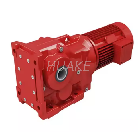
Building on this mechanical foundation, these gear sets are rarely used in isolation. They are frequently integrated directly with electric motors to create a unified Bevel Gear Motor. This electromechanical integration eliminates the need for external couplings and belts. It provides a compact, perfectly aligned, and sealed drive solution ready for deployment in harsh manufacturing environments.
Looking at the broader industrial landscape, there is a massive shift toward sustainable manufacturing. Global energy regulations, like the widespread adoption of IE3 and IE4 motor efficiency standards, are forcing facility managers to scrutinize every component for power loss. The industry trend is moving rapidly away from friction-heavy legacy systems toward rolling-contact mechanisms.
Furthermore, the rise of factory automation demands smaller machine footprints. Equipment designers are under immense pressure to deliver higher torque in tighter spaces. The right-angle configuration perfectly aligns with this trend, allowing for modular, space-saving machine designs. Predictive maintenance is also shaping the future of these drives. Modern gearboxes are increasingly fitted with vibration and thermal sensors, allowing operators to monitor the health of the internal gear mesh in real-time and prevent catastrophic line failures.
For procurement managers and facility operators making bottom-of-funnel purchasing decisions, understanding how different technologies compare is crucial. The initial capital expenditure is only one part of the equation. Efficiency, routine maintenance, and overall lifespan dictate the true cost of ownership. Below is a core comparison of common right-angle solutions.
| Gear Type | Average Efficiency | Friction Type | Noise & Vibration | Best Application Scenario |
|---|---|---|---|---|
| Helical Bevel | 95% - 98% | Rolling | Very Low (Whisper quiet) | Continuous duty, high torque, energy-sensitive operations. |
| Worm Gear | 50% - 80% | Sliding | Low to Medium | Low budget, infrequent use, self-locking requirements. |
| Straight Bevel | 90% - 95% | Rolling / Impact | High (Whining at high speeds) | Low-speed mechanical linkages, manual hand-cranks. |
A well-engineered Helical Bevel Gearbox operates primarily on rolling friction. The precise meshing of the curved teeth allows power to transfer with minimal sliding. While worm gears might be cheaper to purchase upfront, the energy lost as waste heat translates directly into higher electricity bills. Over a multi-year operational lifespan, the energy savings provided by a rolling-contact system almost always offset the higher initial price tag.
When industrial applications demand rigorous performance, engineers frequently specify a Spiral Bevel Gear Reducer. This terminology refers to a drive unit utilizing the curved tooth geometry to reduce motor speed while simultaneously multiplying torque. The advantages of this system are deeply rooted in its physical design.
High Torque Density in a Compact Footprint: Torque density refers to the amount of rotational force a gearbox can transmit relative to its physical size. Because the spiral tooth design allows multiple teeth to mesh simultaneously, these reducers handle immense loads without stripping the gear teeth. For example, a compact unit like the KA47 series can deliver exceptional performance for small machinery. It typically handles torque outputs up to 400 Nm and offers reduction ratios ranging from 5.36 to 32.22, all while maintaining a 95 percent efficiency rate. This empowers machinery designers to specify smaller, lighter units that still meet punishing industrial requirements.
Longevity and Low Wear Rate: Mechanical wear is the ultimate enemy of industrial uptime. The gradual engagement and superior load distribution of spiral teeth drastically reduce the localized stress that causes metal fatigue. Additionally, because these units run significantly cooler than worm gears, the internal lubricating oil maintains its protective viscosity for much longer periods. This synergy of low mechanical stress and optimal lubrication leads to an exceptionally long operational lifespan.
Smooth and Quiet Operation: Occupational safety regulations strictly monitor decibel levels in modern factory environments. Equipment generating excessive noise requires workers to wear heavy hearing protection and disrupts floor communication. The smooth rolling action mitigates the clashing sounds typical of straight-cut gears, ensuring compliance with workplace noise standards.
Specifying a right-angle system requires a careful analysis of mechanical engineering principles. Buyers and system designers must evaluate several critical parameters to prevent premature failure. Instead of relying on guesswork, use this practical framework for your next project.
Step 1: Match Metallurgy to Shock Loads. Standard industrial gears are rarely machined from basic mild steel. Look for manufacturers utilizing high-grade alloy steels like 20CrMnTi. Ensure the components undergo a carburizing and quenching heat treatment. This process infuses carbon into the surface, creating a highly hardened outer case to resist wear, while the inner core remains relatively ductile to absorb sudden shock impacts without shattering.
Step 2: Calculate Exact Thrust Loads. Any angled gear tooth generates axial thrust forces. When the teeth push against each other to transmit torque, they simultaneously try to push the gears apart along their respective shafts. Therefore, the housing cannot rely on standard ball bearings. You must specify heavy-duty tapered roller bearings capable of absorbing both the radial weight of the shaft and severe axial thrust.
Step 3: Determine Thermal and Lubrication Needs. Maintaining a microscopic hydrodynamic film of oil between the metal surfaces is critical. Depending on the operating speed and mounting position, choose between splash lubrication or forced-feed systems. High-quality synthetic gear oils are generally required to manage the shear forces present. Maintaining the correct fluid level is the single most important factor in preventing premature bearing wear.
When consulting with power transmission experts, engineers frequently encounter the K Series Gearbox. This is a widely recognized modular configuration representing the pinnacle of hybrid gear technology.
This series is characterized by a highly robust cast-iron housing, designed using advanced finite element analysis to dampen vibration and maintain strict internal alignment under heavy loads. One of its greatest strengths is modularity. It integrates a helical gear stage with a spiral bevel gear stage within a single housing, allowing for an exceptionally wide range of reduction ratios. It offers flexible mounting options including foot-mounted, flange-mounted, or torque-arm configurations.
For facilities looking to modernize their infrastructure, this configuration is the premier upgrade path for aging worm gear systems. Its standardized dimensions often allow it to serve as a drop-in replacement. Plant managers can instantly boost machinery torque output, standardize their spare parts inventory, and significantly reduce long-term electrical consumption.
A helical bevel gear offers unmatched efficiency and reliability for right-angle power transmission. By blending the directional capabilities of a conical gear with the smooth engagement of helical teeth, these drive units provide better torque density and last significantly longer than traditional alternatives.
Upgrading your mechanical systems to utilize this technology can drastically save energy, minimize workplace noise, and reduce costly machine maintenance downtime. Taking the time to evaluate load requirements, lubrication needs, and mounting configurations ensures your industrial operations run smoothly and profitably day after day. If you are ready to eliminate power loss and optimize your machinery's footprint, explore the high-performance right-angle solutions from Huake Gearbox to find the exact specifications for your heavy-duty applications.
In practical industrial applications, yes. They generally refer to the exact same mechanism, which is a gear with curved teeth situated on a conical surface to transmit power at a right angle. The confusion often stems from CAD software and mathematical modeling. In specific engineering software, helical conical might refer to a specific mathematical generation method for the tooth profile. Spiral bevel is the standardized mechanical term used by manufacturers. For purchasing and operational purposes, they represent the same highly efficient drive.
Yes. Because these gears are highly efficient and rely on rolling friction rather than sliding friction, they are fully reversible and can be easily back-driven. Unlike high-ratio worm gears which often possess self-locking characteristics, a helical bevel system will not hold a load in place when the motor power is removed. If your application requires the load to be held stationary when powered down, you must integrate an external mechanical brake into the motor system.
While mechanical superiority belongs to the rolling-contact gear in almost every metric, a worm gear may be chosen under very specific constraints. You should specify a worm gear only if the upfront budget is the absolute strictest limitation, if the drive will operate very infrequently, or if the application explicitly requires a self-locking mechanism to prevent back-driving without the use of an external brake. For continuous or energy-sensitive applications, the hybrid right-angle design is always the correct choice.
Maintenance is relatively straightforward but absolutely critical for longevity. The primary requirement is adhering to a strict lubrication schedule. Routine oil changes using the manufacturer-specified synthetic gear oil are necessary to remove microscopic metal wear particles and maintain the oil's protective viscosity. Maintenance personnel should conduct regular vibration analysis and thermal monitoring to detect early signs of bearing fatigue. Ensuring that the input and output shafts remain perfectly aligned within tolerance during operation will prevent excessive axial loads.
When properly sized for the application and rigorously maintained, these units are designed to last for decades. It is common for high-quality industrial reducers to operate continuously for 20,000 to 50,000 hours before requiring a major overhaul or bearing replacement. The lack of sliding friction significantly reduces internal wear compared to alternative gear types.
Absolutely. The gradual, sweeping engagement of the curved teeth makes them ideal for high-speed power transmission. Unlike straight-cut gears that generate severe vibration and whining noises at high rotational speeds, this specific geometry maintains smooth, quiet operation even when driven by high-RPM electric motors.


