
- All
- Product Name
- Product Keyword
- Product Model
- Product Summary
- Product Description
- Multi Field Search


Views: 0 Author: Site Editor Publish Time: 2026-10-17 Origin: Site


Need massive torque in a confined envelope? Mechanical engineers face this exact design problem daily on the drafting board. Standard motors frequently stall or suffer premature failure under heavy continuous loads. Designers constantly search for a highly compact and efficient power transmission solution. In this technical walkthrough, we unpack how these specialized units operate. We will analyze their mechanical superiorities and provide a concrete framework for specifying the right hardware for custom builds.
In the realm of mechanical engineering and power transmission, this specialized assembly directly couples a standard electric motor with an epicyclic reduction unit. The primary function drastically reduces the high rotational speed of the electric motor while proportionally multiplying the mechanical torque output.
The nomenclature derives directly from the kinematic movement of the internal components. The gear arrangement physically resembles a solar system. A central gear acts as the sun while multiple smaller gears orbit around it like planets. This specific epicyclic gear train design allows the input shaft and the output shaft to be perfectly aligned coaxially.
For design engineers, this translates to a massive spatial advantage. The power transmission system does not require offset shafts or asymmetrical external housings. By distributing the mechanical load across multiple contact points simultaneously, the system easily handles severe shock forces that would instantly strip the teeth off a standard spur gear mechanism. This inherent durability makes a Planetary Gear Motor an indispensable asset in modern industrial machinery.
Understanding the internal kinematics of the epicyclic gear train is essential for specifying these drives. The mechanism relies on the perfectly synchronized interaction of three primary components securely housed within a cylindrical casing.
Acting as the kinetic heart of the mechanism, the sun gear is typically press-fit or keyed directly onto the motor input shaft. As the motor energizes, this central gear spins at the native high speed of the electrical unit. It serves as the primary power input, delivering high-speed rotational energy to the surrounding components.
Surrounding the central input are multiple planet gears. The ultimate load requirements dictate the exact number, usually three to five. These gears mesh continuously with the sun gear. As the center spins, it forces the planets into rotation. However, these planet gears are mounted onto a rigid precision-machined structure known as the planet carrier.
Because multiple planet gears engage simultaneously, the mechanical stress distributes evenly across several teeth. The planet carrier connects directly to the final output shaft. As the planet gears orbit the center, the carrier rotates at a significantly reduced speed, delivering the multiplied torque directly to the driven payload.
The entire internal assembly is enclosed by the ring gear, occasionally referred to as the annulus. This stationary outer cylinder features gear teeth machined into its internal circumference. The orbiting planet gears mesh with these internal teeth. Specifically, the stationary nature of the ring gear forces the planet gears to walk along its inner perimeter. This constrained mechanical environment dictates the precise mathematical speed reduction and guarantees structural integrity under heavy loads.
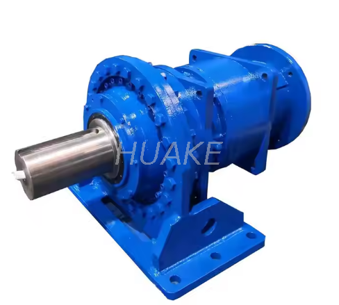
When specifying components for automated machinery, every ounce of weight and every millimeter of space must be justified. The planetary configuration offers several empirically proven advantages over alternative power transmission methods.
The most significant engineering advantage of this architecture is its phenomenal torque density. In a traditional spur gear setup, the entire mechanical load transfers through a single point of contact between two mating gear teeth. In stark contrast, a planetary system shares the load across multiple gears. If a system utilizes three planet gears, the load on any single gear tooth is theoretically reduced by two-thirds. This allows the mechanism to act as a highly effective High Torque Drive capable of moving massive industrial loads without catastrophic tooth shear. High-performance industrial series routinely achieve output torques exceeding 2000 Nm within remarkably compact housings.
Space is a premium commodity in modern hardware design. Because the sun, carrier, and ring share the exact same central axis, the resulting Planetary Gearbox is perfectly cylindrical and sits inline with the motor body. This coaxial arrangement drastically reduces the radial footprint of the drive system. For applications like automated guided vehicles or aerospace actuators, this high torque-to-volume ratio is absolutely necessary.
High-quality planetary systems are CNC-machined to exacting tolerances to minimize sliding friction. A single-stage reducer can frequently achieve mechanical efficiency ratings of 95 to 97 percent. Furthermore, because multiple teeth mesh simultaneously, the system exhibits extremely low backlash. Premium industrial units boast backlash ratings of less than 3 arc-minutes. This ensures that when the motor stops, the output shaft holds its exact coordinate without mechanical deviation.
To make an informed purchasing decision, engineers must benchmark planetary systems against their most common alternative. While both serve the fundamental purpose of speed reduction, their structural differences dictate vastly different use cases.
| Feature and Specification | Planetary Gear Motor | Spur Gear Motor |
|---|---|---|
| Load Distribution | Shared across multiple gears for high load capacity | Concentrated on a single gear tooth for light loads |
| Torque Capacity | Exceptionally High up to 2000 Nm | Low to Moderate |
| Shaft Alignment | Coaxial inline with motor | Offset parallel shafts |
| Space Requirement | Compact cylindrical footprint | Bulky requiring more radial space |
| Backlash and Precision | Very Low under 3 arc-minutes | Moderate to High |
| Efficiency Per Stage | 95 to 97 percent | 90 to 94 percent |
If your application involves heavy lifting, constant starting and stopping under payload, or high-impact shock forces, the planetary design is the objective choice. Spur gears are strictly suited for continuous light-duty applications where space is not a constraint. Consequently, while planetary systems carry a higher initial procurement cost due to complex internal machining, their extended lifespan and superior efficiency yield a significantly better long-term return on investment.
Recent market analyses highlight a defining shift in power transmission. The global market for epicyclic drive systems is expanding rapidly, fueled by the aggressive electrification of commercial vehicles and the miniaturization of factory automation. As collaborative robots and automated guided vehicles become ubiquitous on the factory floor, engineering tolerances are shrinking. The prevailing trend emphasizes maximizing torque density. Engineers are tasked with extracting more rotational force from lighter housings without compromising thermal stability. This relentless demand pushes these specialized drives into the spotlight across several advanced sectors.
In industrial robotics, precise movement is mandatory. Planetary systems provide the near-zero backlash required for exact repeatability. When a robotic arm must return to the exact same coordinate thousands of times a day to perform a weld, the rigidity of the epicyclic gear train ensures the system does not drift out of calibration.
The electromobility sector relies heavily on these systems. In electric mobility hubs, a miniature planetary system housed directly within the wheel casing allows a small electric motor to generate massive starting torque. Similarly, heavy industry equipment must operate continuously under extreme stress. Conveyor belt drives and industrial mixers utilize the robust load-sharing characteristics of the planetary design to prevent mechanical failure. An Industrial Motor paired with an epicyclic gearbox has become the gold standard for surviving these harsh operating environments.
Transitioning from understanding the theory to actually procuring the correct hardware requires a systematic approach. Specifying the wrong unit can lead to premature mechanical failure or erratic motion control. When communicating with suppliers, engineers must define several strict parameters to ensure a perfect fit.
The foundational step establishes the baseline kinetic requirements of your payload. You must determine the continuous torque, which is the constant rotational force required to keep your load moving during normal operation without overheating. Equally important is the peak stall torque, the maximum temporary force required to overcome initial static friction. Finally, dictate the exact output speed required at the final driven shaft.
The gear ratio is the mathematical relationship between the input speed of the motor and the output speed of the gearbox. Selecting the correct ratio is a delicate balancing act. Industrial units typically offer standard single-stage ratios from 3:1 to 10:1, while multi-stage configurations can easily exceed 1000:1 for extreme reduction. Furthermore, frame sizes must match the physical envelope of your machine. Standard flange sizes often range from 42mm up to 220mm, providing scalable options for different payload capacities.
The physical environment dictates the external materials, seals, and lubricants required. If the Geared Motor will face dust or moisture, you must specify the correct Ingress Protection rating, such as IP65 for washdown environments. In addition, high-heat industrial ovens require specialized synthetic lubricants that maintain viscosity under severe thermal stress.
Yes, by reversing the polarity of the direct current electric motor, or by altering the phase sequence in an alternating current motor, the gearbox will seamlessly drive in the opposite direction. The internal mechanics are completely symmetrical, meaning they transmit torque equally well in both clockwise and counter-clockwise rotations without suffering mechanical degradation.
Backlash is the slight clearance between the mating teeth of the gears inside the gearbox, typically measured in arc-minutes. A microscopic amount of space is required to allow for lubrication and prevent binding due to thermal expansion. Excessive backlash causes a slight delay in motion when the motor reverses direction. High-precision units are machined to extremely tight tolerances to achieve very low backlash, which is vital for precise positioning tasks.
In a standard configuration where the ring gear is held stationary, the gear ratio is calculated using the number of teeth on the sun gear and the ring gear. The formula is simply one plus the ratio of ring gear teeth to sun gear teeth. For example, if the ring gear has 60 teeth and the sun gear has 20 teeth, the ratio is one plus three, resulting in a 4:1 total reduction.
Due to the multiple gear meshes occurring simultaneously, planetary gearboxes can generate a distinct whining noise at very high input speeds. However, modern manufacturing techniques such as helical gear cutting and optimized tooth profiles significantly reduce operating noise. High-quality industrial units run exceptionally smoothly and quietly, often remaining well below 65 decibels even under full load.
Maintenance requirements depend heavily on the size and application. Most fractional-horsepower units used in light automation are completely sealed and lubricated for life, requiring zero maintenance. Conversely, large-scale heavy industrial applications subjected to high continuous loads require periodic maintenance. This typically involves draining and replacing the gear oil at manufacturer-specified intervals and visually inspecting the output shaft seals for leaks.
Ultimately, an epicyclic drive system is the premier choice when a project demands immense rotational force in a confined space. These systems offer unmatched precision, durability, and efficiency. By carefully evaluating your torque, speed, and environmental needs, you can select the perfect drive system to ensure your next engineering project operates flawlessly. For engineers seeking robust and high-precision power transmission solutions, exploring the comprehensive catalog at Huake Gearbox provides access to industry-leading hardware tailored for demanding automation and industrial applications.


