
- All
- Product Name
- Product Keyword
- Product Model
- Product Summary
- Product Description
- Multi Field Search


Views: 0 Author: Site Editor Publish Time: 2026-10-20 Origin: Site


Most electric motors spin far too fast to move heavy loads. This inherent lack of pushing power causes immediate machinery failure if left unaddressed. A Gear Reducer safely bridges this mechanical gap. It translates raw, uncontrollable speed into usable, heavy-duty force. In this comprehensive guide, we break down the core purpose of these essential devices. We will explore how their internal mechanisms function and detail the practical steps required to select the precise equipment for your facility's operational demands.
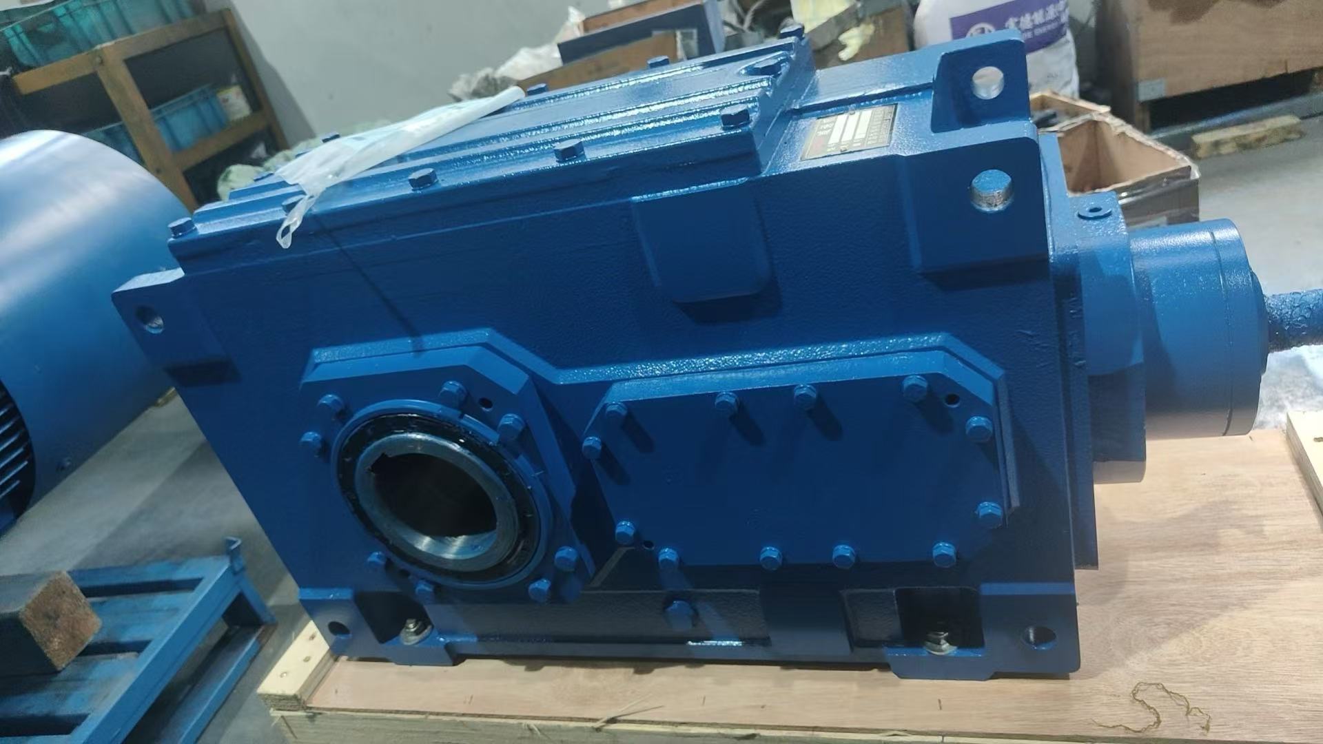
To truly understand the mechanical foundations of modern manufacturing, one must first grasp why direct-drive systems often fail. Industrial machinery operates under rigorous parameters that standard electrical components simply cannot meet alone. Consequently, the reducer acts as the vital translator between the high-speed power source and the slow, heavy application.
Standard alternating current motors feature specific pole configurations that dictate their base speed. In regions utilizing 60Hz power grids, a standard four-pole motor runs at approximately 1750 to 1800 revolutions per minute. While this rapid rotation is excellent for generating raw kinetic energy, it is entirely unsuitable for most mechanical applications.
Picture a quarry conveyor belt loaded with tons of jagged limestone. Connecting a high-speed motor directly to that belt's drive pulley would instantly force the system into a dangerous sprint. This sudden acceleration would destroy the transported material, snap the belt, and shatter the mounting hardware. The primary function of the reduction unit is stepping down this high rotational speed to a manageable level. By utilizing internal gear sets with specific tooth counts, the device mechanically slows the output shaft. This allows that same high-speed motor to drive a massive chemical mixer at a steady 30 revolutions per minute.
Speed reduction represents only half of the engineering equation. The second, and arguably more critical, function is force amplification. Torque is the measure of rotational force. It is the actual pushing or pulling muscle required to move a physical, static load from a dead stop.
According to the laws of physics, power remains constant across a closed system, minus minor efficiency losses due to internal friction. Because the horsepower from the motor remains relatively constant, when the speed decreases, the torque must increase proportionally. This principle is precisely why the equipment is frequently referred to as a Torque Multiplier. It grants a relatively small, inexpensive motor the massive rotational leverage needed to crush solid rock, lift industrial elevators, or move tons of bulk agricultural grain.
Beyond simply altering speed and force, a well-engineered unit optimizes the entire mechanical ecosystem. Directly driving heavy loads with standard motors often leads to severe energy waste. The motor draws excessive electrical amperage as it struggles to overcome the initial inertia of the heavy load, leading to heat generation and wasted electricity.
Specifically, properly specified components ensure that your Power Transmission system operates with minimal energy loss. By mechanically aligning the motor’s optimal running speed with the specific torque requirements of the driven equipment, the entire system operates at peak electrical efficiency. This strategic alignment reduces long-term utility costs and minimizes the carbon footprint of the facility.
While the external housing often looks like a simple, rugged metal block with two protruding shafts, the internal mechanics are highly precise. Understanding how these internal components interact is essential for procurement specialists and maintenance teams alike.
The operational output of the drive unit is entirely dictated by its gear ratio. This ratio represents the mathematical relationship between the number of teeth on the input gear and the driven gear.
For example, consider a transmission system with a 10:1 gear ratio. The electric motor must turn exactly ten times to rotate the output shaft just one time. If a 1750 revolutions per minute motor is attached to this unit, the output speed will be exactly 175 revolutions per minute. Simultaneously, the torque output multiplies by a factor of ten, excluding minor frictional losses. This predictable relationship allows engineers to design complex automated systems with exact specifications.
A standard unit consists of several critical components, all manufactured to strict microscopic tolerances:
Not all mechanical challenges are identical. Because industrial demands vary wildly, manufacturers produce distinct types of drive units. Selecting the correct internal geometry is a critical engineering decision that impacts both upfront cost and long-term reliability.
| Gear Type | Primary Advantage | Efficiency Level | Ideal Industrial Application |
|---|---|---|---|
| Worm Gear | Cost-effective right-angle drive, high shock absorption, self-locking capability. | Moderate to Low | Basic lifting mechanisms, inclined packaging conveyors, light automation. |
| Helical Gear | Incredibly smooth operation, highly durable for continuous heavy-duty loads. | High, often exceeding 95% | Large-scale extruders, massive liquid pumps, continuous bulk material handling. |
| Planetary Gear | Massive torque density within a highly compact, lightweight footprint. | High | Servo-motor automation, robotic arms, wind turbines, mobile construction vehicles. |
| Bevel Gear | High-efficiency right-angle power transfer without the friction losses of worm gears. | High, well above 94% | Right-angle heavy conveyors, mining crushers, space-constrained heavy machinery. |
Looking at current industry trends, the global push toward energy conservation and smart manufacturing has fundamentally elevated the role of these mechanical interfaces. We are rapidly moving away from purely mechanical setups. Modern industrial facilities increasingly pair high-efficiency Industrial Gearbox units with internet-connected sensors. These smart systems monitor real-time vibration and thermal data.
This evolution focuses on intelligent torque management that aligns with strict IE3 and IE4 energy efficiency regulations. By analyzing data trends, facility managers can predict component wear before a catastrophic failure occurs. This proactive approach minimizes carbon footprints while maximizing production uptime, transforming standard drive units into critical nodes of the smart factory ecosystem.
The theoretical mechanics of speed reduction directly translate to tangible industrial capabilities. Without these robust devices, modern mass production, global logistics, and automated infrastructure would instantly grind to a halt.
In sprawling logistics centers and deep underground mining operations, conveyor belts must move massive amounts of weight at highly specific speeds. The reduction unit ensures the belt moves at the exact feet per minute required for safe transport. Furthermore, starting a fully loaded conveyor requires a massive spike in torque to overcome static friction. The internal gears provide this necessary mechanical leverage, preventing the electric motor from stalling upon startup.
Automated assembly lines rely entirely on precise timing and exact spatial positioning. Whether indexing glass bottles for liquid filling or pressing automotive chassis parts together, the machinery demands controlled speed and unyielding rotational force. These drive systems allow for this exact control, ensuring complex manufacturing processes remain perfectly synchronized.
In extreme environments, equipment faces severe physical punishment. Rock crushers, agricultural grain augers, and industrial cement mixers face aggressive shock loads every single day. The purpose of heavy-duty transmission units in these sectors is providing unyielding torque while acting as a mechanical shield. They protect the delicate electric motor from harsh vibrations and sudden jams inherent in processing raw materials.
Attempting to bypass proper mechanical engineering principles leads to catastrophic equipment failure. Engineers design systems with these units because the alternatives are both mechanically and economically unviable.
If a standard motor connects directly to a heavy, slow-moving load, it will desperately attempt to draw excessive electrical current to generate the required torque. Because standard alternating current motors are not designed to produce high torque at low speeds natively, this excess current rapidly converts to intense heat. The internal temperatures will spike dramatically, melting the delicate copper wire insulation. This inevitably results in a violent electrical short circuit and complete motor burnout.
The theoretical alternative to using a reduction unit is purchasing a custom-built, low-speed, high-torque electric motor. However, these specialty motors are physically gigantic, incredibly heavy, and prohibitively expensive. In contrast, utilizing a standard four-pole motor paired with a reduction unit allows facilities to drastically reduce initial capital expenditure. It also lowers ongoing electricity bills and ensures replacement parts are readily available.
Selecting the correct mechanical components is a critical engineering decision. An improper selection can lead to shattered gears and massive financial loss. Instead of relying on guesswork, follow this objective evaluation process.
The most critical step is determining the precise amount of rotational force required to move your load. You must calculate both the continuous running torque and the peak starting torque of your driven equipment. Do not simply match the motor horsepower; the actual twisting force at the output shaft dictates the gearbox size.
Calculating the raw torque is only the baseline. Industrial environments subject machinery to fluctuating stresses, which is why applying a Service Factor is mandatory. This safety multiplier accounts for the type of load, daily operation hours, and the frequency of start-stop cycles. A water pump running eight hours a day might require a minimal Service Factor of 1.0. Conversely, a heavy stamping press operating continuously under violent shock loads requires a Service Factor of 2.0 or higher. Ignoring this will inevitably result in sheared gear teeth.
Once torque and Service Factors are established, match these numbers to real-world equipment capabilities. For continuous heavy-duty operations, engineers often specify robust configurations like the HB Series industrial gear units. These advanced systems offer parallel or right-angle shaft configurations and accommodate massive torque capacities up to 470,000 Nm. With ratio ranges spanning from 1.25 to 450, these specific industrial grades ensure exact speed matching for large-scale extruders or heavy conveyors.
Finally, ensure the input flange physically matches your motor's standard frame size for perfect shaft alignment. You must also determine the mounting orientation. Whether foot-mounted, flange-mounted, or shaft-mounted, the physical footprint must integrate seamlessly into your existing machinery layout without restricting maintenance access.
Purchasing the correct equipment is only the first half of the equation. Executing a rigorous, proactive maintenance program guarantees a high return on your investment. Friction, thermal expansion, and metal fatigue will eventually degrade the system if neglected.
Lubrication is the absolute lifeblood of any mechanical system involving intersecting metal gears. Gear oil creates a microscopic hydrodynamic film between the gear teeth, preventing direct metal-on-metal contact. Additionally, the fluid acts as a vital cooling agent, absorbing intense heat and dissipating it through the outer metal housing.
Routine oil changes are non-negotiable. For standard mineral oils, the first oil change must occur after the initial 500 hours of operation to flush out microscopic metal shavings generated during the break-in period. Subsequent changes should occur every 2,500 to 3,000 hours. Always conduct visual inspections. If the oil appears milky, indicating water ingress, or smells burnt, indicating thermal breakdown, an immediate flush is required.
Predictive maintenance relies heavily on monitoring the physical behavior of the Speed Reducer during normal operation. Two reliable indicators of impending mechanical failure are abnormal vibrations and uncharacteristic temperature spikes.
Every unit has a baseline operating temperature. While it is normal for a heavily loaded unit to run warm, surface temperatures exceeding 200 degrees Fahrenheit usually indicate severe underlying issues like bearing failure. Furthermore, high-frequency vibrations often point to internal bearing defects, while low-frequency vibrations typically indicate shaft misalignment. Implementing monthly thermal imaging and spectral vibration checks allows engineers to schedule targeted repairs during planned downtime.
The core purpose of these mechanical transmission systems is bridging the difficult gap between high-speed electric motors and the high-torque demands of real-world industrial machinery. By safely stepping down speed and multiplying rotational force, they make modern automated manufacturing possible.
Choosing the correctly sized unit, applying the proper service factors, and adhering to strict maintenance schedules saves vast amounts of money. It protects your facility's valuable infrastructure and ensures daily operational efficiency remains highly profitable.
If you are designing a new facility or upgrading aging infrastructure, selecting the precise equipment is your most critical step. Do not wait for a catastrophic failure to evaluate your machinery. Assess your current power transmission setups today, and explore the comprehensive range of robust, high-efficiency solutions at Huake Gearbox to find the exact specifications, mounting configurations, and torque capacities required for your most demanding projects.
A: While the primary function of these devices is to decrease rotational speed, the mechanical principles of gear ratios can absolutely be applied in reverse. By connecting the motor to the larger gear and driving the smaller gear, the device functions as a speed increaser, often referred to as an overdrive unit. However, the laws of physics dictate an inverse relationship between speed and torque. Multiplying the speed by a factor of two cuts the available torque in half, minus friction losses. Speed increasers are highly specialized and typically used in applications like wind turbines or centrifugal compressors.
A: In the industrial manufacturing sector, the terms are practically interchangeable. A gearbox is the broad, generic term for any enclosed system of gears housed within a rigid casing. A gear reducer is simply a specific type of gearbox whose primary engineered function is to reduce the input speed from a prime mover. Therefore, all gear reducers are gearboxes, but not all gearboxes are gear reducers. When speaking with engineers, using either term will generally be understood perfectly.
A: Mechanical failure is rarely instantaneous. It is almost always preceded by clear, measurable warning signs. The most common auditory indicators include abnormal grinding, whining, or heavy clunking noises, which suggest advanced gear tooth wear or bearing fatigue. Visual signs include oil pooling around the base of the unit, indicating ruptured synthetic seals. Thermally, if the unit exterior is suddenly too hot to touch, internal friction has exceeded safe operating parameters. Routine oil analysis can also reveal microscopic metal particles suspended in the lubricant, which is definitive proof of internal degradation.
A: This is a very common point of confusion. The device does not reduce the total amount of mechanical power generated by the motor. Instead, it changes the specific form of that power. According to the conservation of energy, the total horsepower remains constant throughout the system, shifting the balance from high speed and low torque to low speed and high torque. However, no mechanical system is perfectly efficient. Depending on the gear type, a small percentage of the motor horsepower is lost as heat and friction during transmission.
A: When properly specified and rigorously maintained, a high-quality industrial unit can easily last 10 to 15 years in continuous operation. The actual lifespan depends heavily on the operating environment, the accuracy of the applied Service Factor during the initial selection, and strict adherence to lubrication schedules. Units subjected to extreme shock loads, high ambient temperatures, or irregular oil changes will experience significantly shortened operational lifespans.
A: Yes, many units are specifically designed for vertical mounting, which is common in applications like industrial mixers or agitators. However, you cannot simply take a standard horizontal unit and turn it on its side. Vertical mounting requires specific internal modifications, such as specialized bearing configurations to handle downward thrust loads and modified lubrication systems to ensure oil reaches the topmost gears and bearings. Always specify the exact mounting orientation when ordering the equipment to ensure proper internal engineering.


