
- All
- Product Name
- Product Keyword
- Product Model
- Product Summary
- Product Description
- Multi Field Search


Views: 0 Author: Site Editor Publish Time: 2026-10-15 Origin: Site


Plant operators know the headache of loud, clunky machinery all too well. Gear teeth shearing under heavy loads means unplanned downtime and massive maintenance bills. This intense mechanical friction and deafening noise were eventually solved by a specific innovation involving the geometry of gear teeth. By altering the cut angle, engineers revolutionized how mechanical power moves across heavy machinery.
For modern mechanical designers, understanding this component remains a fundamental requirement on the factory floor. A helical gear is a cylindrical mechanism featuring teeth cut at a precise angle to its face rather than straight across. The primary purpose of this design is to provide smoother, quieter, and vastly more durable power transfer in high-speed, high-load applications.
In this comprehensive guide, we will break down the underlying physics of these components and compare their field performance against traditional spur gears. You will discover the different configurations available and learn exactly how to spec the right components for modern industrial transmission systems.
To fully grasp the mechanism, you must look closely at the physical design. Unlike standard straight-cut units where the teeth align parallel to the axis of rotation, these teeth are machined at a specific angle. Engineers refer to this as the helix angle, typically ranging from 15 to 30 degrees.
This precise geometry fundamentally changes how the mating surfaces interact. Instead of the entire tooth face colliding at once, contact begins at one end of the tooth and smoothly sweeps across the face as the cylinder rotates. This progressive engagement maintains constant, uninterrupted contact between the mating surfaces. The transfer of mechanical force becomes continuous and fluid. It entirely avoids the sudden, jarring impact characteristic of older straight-tooth designs.
While the angled profile provides massive advantages in operational smoothness, it introduces a specific physical byproduct known as axial thrust. As the angled teeth push against one another to transmit rotational torque, a secondary sliding force is generated along the axis of the shaft.
In real-world industrial design, this lateral force must be strictly managed. Engineers mitigate this by integrating heavy-duty tapered roller bearings into the housing. When designing a transmission unit, the internal bearing configuration is specifically engineered to counteract this thrust. This ensures the internal shafts remain perfectly aligned even when subjected to extreme continuous operational stress.
Imagine standing next to a high-speed packaging line in a bottling plant. The deafening whine of traditional straight-cut gears causes rapid operator fatigue and requires heavy ear protection. The gradual engagement of angled teeth eliminates this characteristic howling noise. By minimizing the violent impact of metal surfaces colliding, the system operates at a drastically lower decibel level. Beyond just protecting human hearing, eliminating this vibration protects delicate surrounding electronic sensors and prevents structural metal fatigue in the machine chassis.
In a traditional setup, the entire transmission load is often carried by a single pair of mating teeth at any given microsecond. The angled design changes this dynamic entirely. A higher contact ratio ensures that multiple teeth share the operational load simultaneously. Distributing the immense torque across a larger surface area vastly reduces the localized pressure on any individual metal tooth. This physical distribution is exactly what prevents premature wear, pitting, and catastrophic tooth breakage when a machine takes on heavy sudden loads.
Due to the reduction in dynamic shock and superior load distribution, these components are the definitive choice for high-velocity systems. When straight gears are pushed to high revolutions per minute, they tend to vibrate aggressively. This leads to rapid degradation and highly inefficient power transfer. Angled teeth maintain structural stability and constant contact at extreme speeds, ensuring seamless power delivery without the risk of sudden mechanical failure.
Recent market analyses and engineering reports highlight a massive shift in automated manufacturing. Plants are pushing for higher throughput while facing much stricter occupational noise limits. Consequently, the demand for ultra-compact, high-torque drive systems has skyrocketed.
Today's smart factories require components that deliver extreme power density without expanding the machine footprint. Manufacturers are responding by producing profiles with tight DIN class 4 precision and advanced surface hardening treatments. This evolution aligns perfectly with the global push toward sustainable, energy-efficient automation, ensuring that modern power transmission systems remain compact, whisper-quiet, and highly reliable.
When engineering a drive system, deciding between these configurations is a matter of balancing field performance requirements against manufacturing budgets. Your decision dictates the operational lifespan and efficiency of the entire machine.
| Specification | Helical Profile | Spur Profile |
|---|---|---|
| Tooth Design | Angled | Straight |
| Noise Level | Very Low | High |
| Load Capacity | High | Moderate |
| Speed Capability | Excellent for High-Speed continuous use | Limited to Low or Medium Speed |
| Axial Thrust | Yes | No |
For applications demanding high rotational speeds, angled teeth are strictly required. Their ability to maintain continuous contact prevents the dynamic shock loads that severely limit the speed capabilities of spur designs. Conversely, spur gears remain a viable, cost-effective option for low-speed applications where noise generation and heavy vibration are not critical concerns.
The gradual sweeping engagement of an angled tooth introduces a degree of sliding friction. This friction generates more internal heat compared to the simple rolling friction of a spur gear. These systems require high-quality specialized lubrication, often synthetic oils, to dissipate heat and maintain thermal stability. While there is a fractional drop in raw mechanical efficiency due to this friction, it is heavily outweighed by massive gains in transmission smoothness and overall load capacity.
The foundational design of the angled tooth has been adapted into several distinct configurations. Each is engineered to solve specific mechanical challenges on the factory floor.
This is the standard configuration featuring a single set of angled teeth on the cylinder face. They are primarily utilized in standard parallel shaft setups to transmit power smoothly. Because they inherently generate axial thrust, they must always be paired with appropriate thrust bearings to keep the shaft securely in place.
To completely solve the issue of axial thrust, engineers developed the double helical design. This layout features two sets of teeth cut at opposing angles on the same gear face, typically separated by a small central gap. The opposing angles generate equal but opposite thrust forces which cancel each other out internally. This ingenious design makes them ideal for massive torque applications like large mining winches where managing thrust with bearings would be mechanically impractical.
Functioning on the exact same physics as double helical designs, herringbone gears do not have a gap separating the opposing teeth. Instead, they form a continuous interlocking V shape. Their primary purpose is to provide maximum power transmission in ultra-heavy equipment such as aggregate crushers and marine propulsion systems. They deliver immense strength within a highly compact footprint.
In heavy industry, standard electric motors output rotational speeds that are far too fast for the driven machinery. Plant engineers rely on a Helical Gear Reducer to precisely decrease the input speed from the motor while simultaneously multiplying the output torque. These reducers act as the muscle for heavy conveyor belts, industrial mixers, and large-scale plastic extruders.
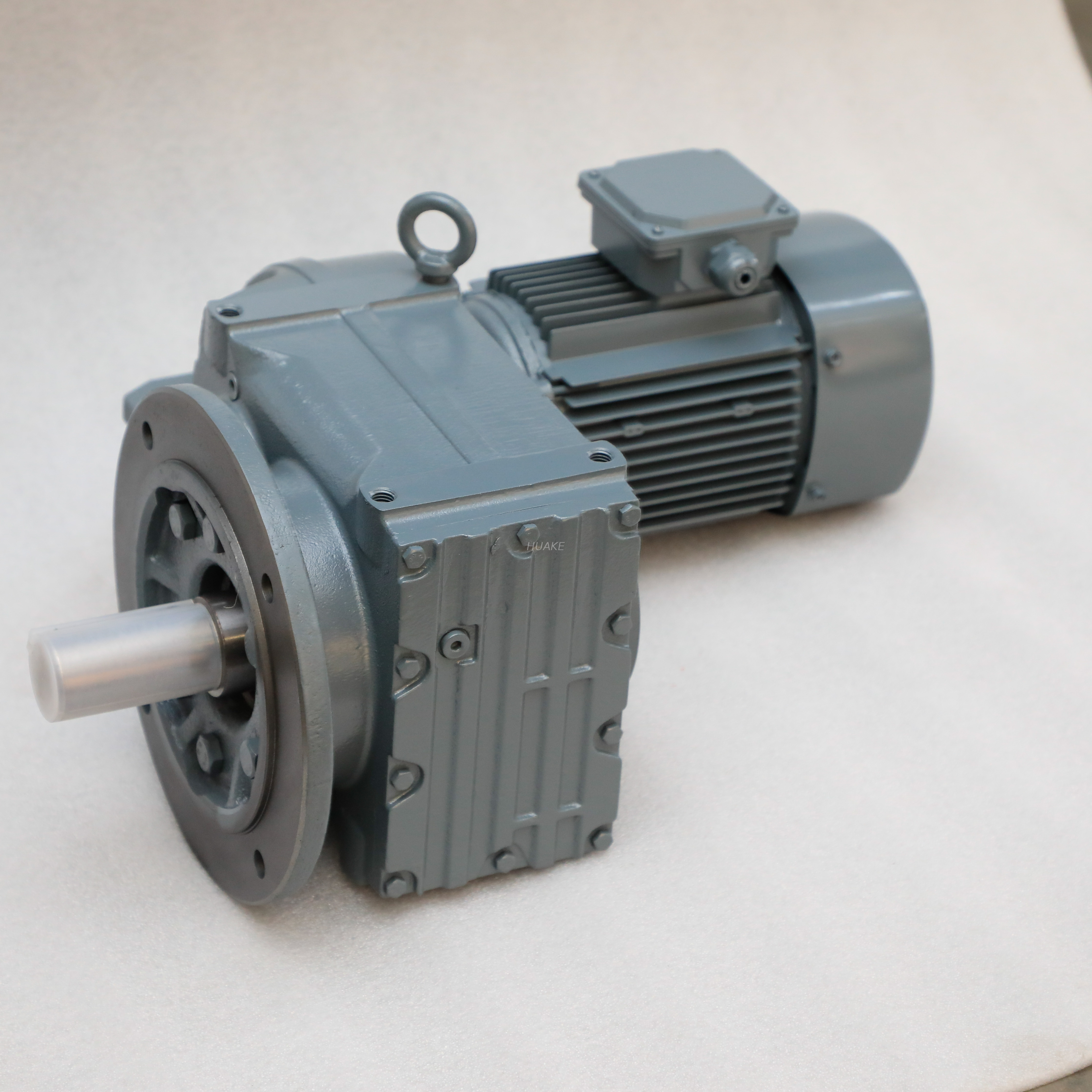
When lateral installation space is highly restricted but massive torque is mandatory, a Parallel Shaft Gearbox is the undisputed standard. For instance, F-Series industrial parallel shaft units are specifically engineered for heavy-duty conveying systems. They utilize multiple stages of angled gears to achieve reduction ratios spanning from 3.81 to 281.71. This specific geometry delivers output torque up to 18,000 Nm, providing the exact mechanical muscle required for overhead cranes and large-scale agitators.
Integrating an electric motor directly with a transmission system creates a highly efficient drive solution. This integration eliminates the need for bulky external couplings and separate base mountings. They offer superior shaft alignment and high efficiency, making them the preferred choice for automated packaging machinery and precision robotics.
Selecting the correct transmission component requires hard data. Over-specifying burns your capital budget. Under-specifying inevitably leads to catastrophic mechanical failure on the production line.
First, define your exact load. Calculate the required output torque in Nm and the target output speed. The ratio between your motor input speed and your desired output speed dictates the necessary gear ratio. Always factor in a service margin based on daily operational hours and the likelihood of sudden shock loads. If your heavy-duty conveyor demands 15,000 Nm of torque, ensure the selected unit is rated well above that threshold to handle startup spikes.
Because lateral thrust is inherent to single-angle designs, you must verify the internal engineering of the gearbox before purchase. Ensure that the unit is constructed with high-capacity tapered roller bearings capable of handling the specific thrust loads generated by your machinery. If your application involves massive sudden load spikes, upgrading to a double helical configuration may be mechanically necessary.
The operational longevity of an industrial reducer relies entirely on material integrity and thermal management. Look for internal components forged from high-grade alloy steels like 20CrMnTi. These should be carburized and quenched to achieve a surface hardness of 58 to 62 HRC for maximum wear resistance. Furthermore, strictly verify the lubrication requirements. High-speed continuous operations often necessitate premium synthetic lubricants like ISO VG 220 to effectively maintain the oil film and dissipate the heat generated by sliding friction.
Its primary function is to transmit rotational mechanical power between shafts smoothly and quietly. By engaging teeth gradually, it can handle significantly higher load capacities and rotational speeds than standard straight-cut spur gears without excessive vibration.
When properly sized, manufactured from high-grade carburized steel, and maintained with the correct synthetic lubrication, these industrial transmission units can operate continuously for tens of thousands of hours without significant degradation. Routine oil changes are the biggest factor in maximizing this lifespan.
Direct replacement is rarely possible without modifying the gearbox housing. Because angled teeth generate axial thrust, the existing housing must have adequate space and structural support to accommodate new tapered roller bearings. Simply swapping the gears without upgrading the bearings will lead to rapid shaft misalignment and failure.
Yes, they are engineered to operate efficiently in both rotational directions. This bidirectional capability makes them highly versatile for reversible motors, conveyor systems, and automated machinery that require precise back-and-forth motion control.
The angled cut of the teeth creates a sliding directional vector force along the axis of the gear shaft during operation. This lateral force is a natural byproduct of the geometry and must be safely absorbed by dedicated thrust bearings housed within the gearbox.
Yes, they generally offer much higher mechanical efficiency, often exceeding 95 percent. This is because they produce significantly less sliding friction and generate less internal heat compared to the high-friction perpendicular sliding action inherent in worm gear designs.
The fundamental purpose of this engineering marvel is highly specific yet universally impactful. By altering a simple angle, engineers created a mechanism that ensures quiet, high-capacity, and exceptionally smooth power transmission for the world's most demanding applications. While they require a higher initial investment than traditional straight-cut designs, their operational durability is truly unmatched.
Ready to eliminate excessive noise and frequent maintenance on your factory floor? Upgrading your drive machinery is the most effective step. Whether you need a robust Gear Motor for a packaging line or a heavy-duty parallel shaft unit for bulk material handling, selecting precision-engineered components is crucial. Visit Huake Gearbox to explore industrial solutions tailored to your exact torque and spatial requirements, and let our engineering team help you optimize your facility's reliability.


