
- All
- Product Name
- Product Keyword
- Product Model
- Product Summary
- Product Description
- Multi Field Search


Views: 0 Author: Site Editor Publish Time: 2026-08-17 Origin: Site


Engineers and system designers frequently confront a critical dilemma regarding cost and complexity. They must determine whether a standard gearbox can safely hold a suspended load when the motor completely stops. Alternatively, they wonder if a dedicated, fail-safe mechanical brake is always mandatory.
People often praise worm gearings for their inherent "self-locking" capabilities. However, treating these gear sets as absolute safety braking mechanisms carries severe operational and compliance risks. Misunderstanding static friction limits can lead to catastrophic equipment failure or severe workplace injuries. Industry safety bodies repeatedly warn against this assumption.
This article clarifies the exact physical conditions required for a worm gear reducer to reliably hold a static load. We will explore specific environmental variables that heavily compromise this ability in real-world scenarios. Finally, you will receive a strict decision framework to evaluate your motion control systems properly.
To fully grasp load holding, we must first look closely at the mechanical nature of these unique drives. The architecture inherently relies on sliding friction rather than rolling friction. This fundamental difference dictates how the equipment behaves under stress.
A typical setup places the worm shaft perpendicular to the worm wheel. This 90-degree crossed-axis geometry creates massive inherent resistance. When the motor turns the input shaft, the threaded worm pushes against the wheel teeth. The gear teeth slide against each other. This sliding action generates friction. If you remove power, the load attempts to force the wheel backward against the worm thread. Static friction resists this reverse motion.
Backdriving occurs when the load on the output shaft successfully drives the input shaft. Imagine a heavy conveyor belt stopping on an incline. Gravity pulls the belt downward. The belt transfers this force into the gearbox output shaft. If the internal resistance is too low, the output shaft will rotate. It forces the motor shaft to spin backward. This uncontrolled descent is backdriving.
You must separate static efficiency from dynamic efficiency when designing safety systems. Static efficiency measures the unit at a complete standstill. Dynamic efficiency measures the unit in motion. A specific drive unit might successfully hold a suspended mass while stopped. Static friction is relatively high. However, if that same mass begins falling, dynamic friction takes over. Dynamic friction is always lower than static friction. Consequently, the drive will completely fail to stop a load once it starts moving.
Several distinct factors dictate whether your setup will lock or slip. You cannot rely on a single metric to guarantee safety. We must evaluate four primary engineering variables.
We see an inverse relationship between the gear ratio and the lead angle of the worm thread. Lower ratios, such as 10:1 or 15:1, feature steep lead angles. These steep angles offer very little resistance to reverse forces. They will freely backdrive. High ratios, like 60:1 or 80:1, feature very shallow lead angles. When the lead angle is smaller than the coefficient of static friction, the unit theoretically locks. The physics prevent the wheel from wedging the worm backward.
Engineers often face an unexpected implementation reality. Modern synthetic lubricants and extreme-pressure (EP) gear oils are remarkably effective. They dramatically reduce friction to prevent heat buildup and metal scoring. Unfortunately, they perform this job too well in self-locking applications. The boundary layer created by EP additives lowers the static friction coefficient. They can inadvertently cause a theoretically "locked" drive assembly to slip smoothly backward under load.
You must consider the product lifecycle. Manufacturers purposefully make the worm wheel from softer materials, typically phosphor bronze. The worm shaft consists of hardened steel. During operation, the softer bronze wheel slowly wears down. This wear acts as a sacrificial mechanism to protect the expensive steel shaft. Over time, this degradation alters the precise mesh geometry. The contact patch changes. As a result, the static holding power decreases significantly over the equipment's lifespan.
External system vibrations ruin holding capacity. Physics explains this clearly. Static friction relies on surfaces locking together at a microscopic level. When nearby machinery introduces vibration, it shakes the gear mesh. This dithering effect momentarily breaks the static friction bond. The system instantly transitions to the much lower dynamic friction state. The suspended load will begin to "creep" downward. Even small vibrations cause steady, unstoppable creeping.
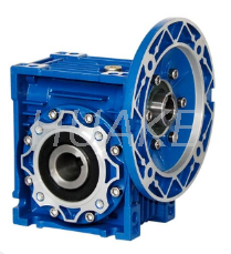
Designers choose from various housing and gearing configurations based on application needs. Each variation uniquely impacts the friction dynamics required for holding loads.
Cast iron housings represent the traditional industrial standard. They are heavy, robust, and absorb shock well. However, many modern applications demand weight savings. If you design packaging machinery or mobile equipment, you will likely evaluate a lightweight aluminum worm gearbox.
Beyond weight reduction, aluminum excels at rapid heat dissipation. It transfers internal heat to the surrounding air quickly. This thermal characteristic directly affects the oil inside. The lubricant stays cooler and maintains a higher viscosity. Thicker, cooler oil slightly increases the internal resistance. Therefore, aluminum enclosures can marginally improve long-term static holding consistency compared to units running dangerously hot.
Sometimes, a pure right-angle drive cannot deliver the required startup torque. Engineers often introduce a hybrid solution. We compare standard units directly against a helical worm gear motor for demanding applications.
This hybrid adds a preliminary helical gear stage before the right-angle stage. The helical addition provides significantly higher torque transfer and overall energy efficiency. It drastically reduces motor amp draw. However, you face a major trade-off. This combined efficiency almost always pushes the unit far above the self-locking threshold. The rolling friction of the helical stage negates the sliding friction resistance of the right-angle stage. When using a hybrid setup, you must mandate an external motor brake to hold any static load safely.
| Configuration Type | Primary Housing Material | Mechanical Efficiency | Self-Locking Potential |
|---|---|---|---|
| Standard Pure Worm | Cast Iron | Low to Medium (40-70%) | High (Ratio dependent) |
| Compact Lightweight | Aluminum | Low to Medium (40-70%) | High (Maintains oil viscosity) |
| Hybrid Helical-Worm | Cast Iron / Aluminum | Medium to High (75-85%) | Very Low (Brake required) |
Assuming a drive unit will act as a permanent brake creates immense liability. We must examine the regulatory and practical risks of this engineering mistake.
General engineering consensus strictly prohibits using gears as safety devices. Organizations like OSHA and ISO publish detailed hoisting guidelines. They classify gearboxes exclusively as power transmission devices. They are never classified as safety brakes. If you design an overhead crane, regulatory codes require dedicated mechanical braking systems. Relying on gear mesh friction violates core safety compliance standards. Inspectors will flag these systems immediately.
Field technicians frequently demonstrate the unreliability of self-locking through the "Tap Test." Imagine a suspended weight perfectly stopped by a 60:1 ratio gearbox. The setup appears entirely secure. A technician walks by and taps the metal chassis sharply with a rubber mallet. The sudden shock wave travels through the frame. It reaches the gear teeth, breaking the static friction instantly. The load drops an inch. In real environments, a passing forklift or a heavy stamping press provides this same shock. The load will inevitably creep downward.
Business risk drives many engineering decisions. Eliminating a dedicated motor brake might save a company $200 per machine. This cost reduction seems attractive during initial prototyping. However, you must weigh this against the consequences of failure. A creeping load can crash into expensive peripheral equipment, causing $50,000 in damage. Worse, an uncontrolled drop endangers human life. The legal and financial liability of omitting a brake far outweighs any minor component savings.
To eliminate guesswork, use this strict evaluation framework. It categorizes applications based on safety and physical forces.
In highly specific, low-risk situations, you can rely on inherent friction.
If your application falls into these categories, you must integrate a fail-safe mechanical brake.
We must treat "self-locking" as a conditional state of friction, not a guaranteed mechanical property. It relies entirely on perfect variables. Lubricant type, tooth wear, and external vibration all actively conspire to degrade holding capacity over time.
When mapping out motion control architectures, you must take definitive next steps. First, calculate your precise load requirements and evaluate gravity's role in your system. Next, deeply evaluate the environmental vibration your machine will experience on the factory floor. Finally, consult directly with your manufacturer to specify the correct braking mechanisms. Do not risk your equipment or personnel on a fragile self-locking assumption. Integrate proper mechanical brakes wherever gravity and safety dictate.
A: Hold torque refers to the static resistance generated by the gear mesh when the motor is off. It measures how much external force the gears can resist before slipping backward. Stall torque is the maximum dynamic load the motor can push before it electrically stalls or the mechanical gear teeth break under extreme rotational stress.
A: No, it does not guarantee anything. A 40:1 ratio provides high resistance because of its shallow lead angle. However, external vibration, wear over time, or highly lubricious synthetic oil can still break the static friction. This causes the system to backdrive unexpectedly.
A: Absolutely not. You must never use it to abruptly stop a heavy, moving mass. The sudden dynamic shock loads will instantly shear the softer bronze gear teeth. It is designed for power transmission, not kinetic energy absorption.


