
- All
- Product Name
- Product Keyword
- Product Model
- Product Summary
- Product Description
- Multi Field Search


Views: 0 Author: Site Editor Publish Time: 2026-10-14 Origin: Site


Did you know unseen mechanical forces quietly power our modern world? Behind almost every automated process or moving mechanical part, there is a robust Drive System doing the heavy lifting. Yet, engineers and procurement managers often struggle to choose the precise motor for their specific operational needs. Specifying the wrong component inevitably leads to costly inefficiencies. It drives up energy consumption and frequently results in catastrophic equipment failure.
In this comprehensive guide, we will explore the vast landscape of power transmission applications. By understanding the mechanical realities of these devices, you can pinpoint the perfect solution for your machinery. This ensures long-term operational stability on the factory floor.
To grasp the sheer breadth of power transmission applications, we must first define the equipment objectively. A gear motor is an integrated electromechanical unit. It consists of an electric motor coupled seamlessly with a gear reducer. This mechanical pairing is specifically engineered to deliver exceptionally high torque at lower horsepower and reduced rotational speeds.
The operational principle of this unit follows a straightforward mechanical sequence. Initially, the electric motor generates high-speed, low-torque rotational kinetic energy. This raw rotational power then enters the gearbox. Inside, a complex series of internal gears systematically reduces the output speed. According to the fundamental principles of mechanical advantage, as the output speed decreases, the resulting torque increases proportionally.
Engineers consistently specify these integrated units rather than standard large-frame motors for a simple reason. Achieving high torque at low speeds with a standard motor requires a massive and prohibitively expensive electrical footprint. By integrating a reducer, facility designers can utilize a much smaller motor to achieve the exact mechanical force required. Ultimately, this saves valuable physical space while drastically cutting electrical energy waste.
The global industrial landscape relies heavily on the controlled power output provided by geared drives. Different sectors face unique environmental and mechanical challenges. Therefore, they require highly specialized configurations to maintain continuous production.
Modern supply chains, sprawling e-commerce fulfillment centers, and rugged mining operations depend entirely on continuous material flow. In these high-stakes environments, a reliable Conveyor Gear Motor is absolutely critical. Applications typically include miles of belt conveyors, heavy-duty roller systems, and complex airport baggage handling networks.
These specific applications require immense starting torque to overcome the static inertia of heavy stationary loads. The drive unit provides the necessary brute force to initiate movement smoothly without stalling the line. Since logistics operations demand unwavering reliability, units deployed in this sector operate on a continuous duty cycle. They run relentlessly and must be engineered with superior thermal dissipation capabilities.
With the rapid implementation of smart factories, mechanical movements must be both powerful and flawlessly repeatable. An Automation Gear Motor is specifically deployed in multi-axis robotic arms, automated guided vehicles navigating warehouse floors, and high-speed assembly line indexing tables.
Unlike bulk material handling, advanced factory automation prioritizes absolute precision control and near-zero mechanical backlash. Drive units used here are frequently paired with sophisticated servomotors to ensure exact spatial positioning. Their miniaturized design allows them to be tucked into tight spaces within robotic joints without compromising the necessary torque.
The food and beverage industry presents some of the most rigorous regulatory challenges in the manufacturing world. Geared drives are heavily utilized in massive industrial mixers, fluid agitators, and high-speed bottling lines.
The primary engineering hurdle in this sector is sanitation. Machinery is frequently subjected to high-pressure chemical washdowns to eliminate bacteria. Consequently, units designed for this sector are typically housed in smooth stainless-steel enclosures boasting maximum ingress protection ratings. They must also utilize specialized food-grade synthetic lubricants to prevent catastrophic product contamination.
Heavy-duty outdoor applications subject mechanical components to extreme environmental stress. Geared power systems are foundational in massive center-pivot irrigation systems, rugged cement mixers, and heavy-lifting construction cranes.
These harsh environments demand uncompromising ruggedness. The equipment must withstand severe mechanical shocks and constant bombardment by abrasive dust. Thick cast-iron housings and heat-treated gear sets are standard requirements. This ensures the machinery does not fracture under the massive torque demands of moving tons of wet earth.
For mechanical engineers and procurement specialists, mapping specific application requirements to the correct internal gear geometry is a critical decision. The internal configuration dictates how power is transmitted and how long the equipment will survive under heavy loads. Selecting an incompatible design often leads to premature bearing failure and unacceptable noise levels.
Helical gears are precisely engineered with teeth cut at a specific angle to the face of the gear. Unlike standard straight-cut spur gears where the entire tooth slams into engagement at once, helical teeth engage gradually. This angled meshing process allows for a remarkably smooth transfer of rotational force.
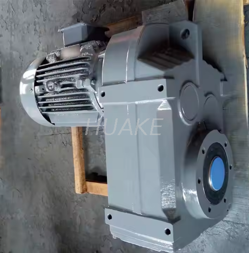
A standard Helical Gear Motor is widely recognized for its exceptional energy efficiency, routinely reaching up to 98 percent. Take the F-Series Helical Gear Motor FA107 as a prime engineering example. Designed for parallel shaft mounting, this specific series delivers immense torque transmission efficiency while fitting into narrow spatial footprints. Because the parallel shaft design minimizes sliding friction, very little kinetic energy is lost as heat. They are heavily utilized in large-scale manufacturing extruders and continuous duty conveyors.
Worm gearboxes utilize a unique perpendicular design consisting of a threaded worm shaft that meshes with a toothed bronze wheel. The most significant engineering advantage of this configuration is its ability to achieve massive speed reductions within a highly compact physical footprint.
Worm gears are inherently self-locking. Due to the severe angle of the sliding friction, the output shaft cannot easily drive the input shaft backwards. This natural braking mechanism is an essential safety feature for vertical hoists and inclined material handling systems. The trade-off for this safety is efficiency. The sliding action generates significant heat, meaning worm gears typically operate at lower efficiencies and require frequent monitoring of synthetic lubricants.
Planetary systems are complex configurations that mimic the solar system. A central sun gear is surrounded by multiple planet gears, all contained within a stationary outer ring gear. As the motor drives the central gear, the outer gears revolve around it, distributing the mechanical load evenly across multiple contact points.
This distributed load geometry allows a planetary system to handle immense torque spikes while maintaining a very small external diameter. Planetary configurations are prized for their extreme torsional stiffness and exceptionally low backlash. These attributes make them the definitive choice for environments requiring absolute precision.
| Gear Configuration | Average Efficiency | Backlash Level | Best Suited For |
|---|---|---|---|
| Helical | 95% - 98% | Moderate | Continuous factory operations, extruders |
| Worm | 50% - 80% | High | Tight spaces, vertical lifting, hoists |
| Planetary |


