
- All
- Product Name
- Product Keyword
- Product Model
- Product Summary
- Product Description
- Multi Field Search


Views: 0 Author: Site Editor Publish Time: 2026-08-16 Origin: Site


Selecting the right gear type is only the first step. Specifying the correct spatial orientation is critical for operational longevity. Engineers often finalize gear ratios and torque ratings but completely overlook mounting geometry. This oversight causes massive mechanical issues. Incorrect mounting positions lead directly to oil starvation, thermal overload, and premature bearing failure.
You cannot rely on guesswork when integrating these drive systems into your plant layout. Gravity influences every internal fluid dynamic. You must understand how spatial orientation alters mechanical behavior. This article provides a definitive, standard-compliant framework. We will help you evaluate and specify the exact mounting position for your equipment.
You will learn how gravity impacts lubrication pathways. We will explain why breather placement matters for pressure equalization. We also cover the standardized M1 through M6 mounting designations. By mastering these concepts, you ensure your mechanical drives run reliably from day one.
Mechanical drives do not operate in a vacuum. Gravity continuously acts upon the internal components. When you change the mounting angle, you drastically alter how the machine sustains itself. Engineers must treat mounting positions as core performance variables. If you ignore this reality, you risk catastrophic equipment failure.
Gravity dictates where oil pools inside the housing. A standard coaxial helical gear reducer relies heavily on splash lubrication. The lowest gears dip into the oil bath. They fling lubricant upward to coat the upper gears and bearings. When you tilt the unit, the oil pool shifts. This shift leaves some gears completely submerged while others remain dry. Starved bearings undergo rapid metal-to-metal contact. This friction causes spalling, galling, and eventual seizure. Forced lubrication systems can solve this, but they require precise engineering based on the specific tilt angle.
Gear units generate significant heat during operation. The housing acts as a primary heat sink. It dissipates thermal energy into the surrounding air. Different orientations alter the available surface area for heat dissipation. If you mount a unit against a wall, you block airflow to one side. Heat then builds up internally. This thermal overload degrades the oil viscosity. Thinner oil fails to separate moving metal parts. You must evaluate how the chosen mounting position interacts with ambient factory airflow.
Internal temperatures fluctuate constantly. Oil expands as it heats up. This expansion increases internal air pressure. Breather valves safely release this pressure. However, proper breather placement relies entirely on mounting orientation. The breather must always sit at the highest point. If you mount the unit upside down without moving the breather, oil submerges the valve. Pressure then builds up inside the casing. This pressure eventually blows out the rubber oil seals. Seal failure causes massive leaks and environmental hazards.
You must anchor your evaluation in risk management. Unplanned downtime ruins production schedules. Replacing a destroyed gear unit consumes valuable maintenance hours. The upfront effort of specifying the correct mounting position costs nothing. It requires only careful communication during the design phase. Getting this specification wrong guarantees rapid mechanical failure.
The industry uses standardized codes to define mounting orientations. These ISO-compliant codes range from M1 to M6. They provide a universal language for engineers and manufacturers. Understanding these codes prevents miscommunication during procurement.
| Position Code | Orientation Description | Primary Risk Factor | Lubrication Strategy |
|---|---|---|---|
| M1 | Horizontal (Baseline) | Minimal | Standard splash lubrication. |
| M2 | Vertical (Input shaft facing up) | Top bearing dry running | High oil level, specialized grease, or double seals. |
| M3 | Inverted (Ceiling mount) | Seal leaks and pressure buildup | Relocated breather to new top. |
| M4 | Vertical (Input shaft facing down) | Top bearing dry running | High oil volume, forced oil pump in severe cases. |
| M5 / M6 | Wall Mounted (Side configurations) | Axial load shifting | Adjusted oil levels, specific drain plug placement. |
M1 represents the baseline configuration. The unit sits flat on the floor. Most standard conveyors and pumps use this setup. M1 requires standard oil volumes. It also offers optimal natural cooling. The oil evenly coats the lower gears, creating a reliable splash effect. Manufacturers test their standard performance ratings based on this exact position.
These positions feature downward or upward facing shafts. They present significant engineering challenges. Gravity pulls oil away from the uppermost bearings. These upper components become highly susceptible to oil starvation.
Evaluation criteria for vertical mounts include specialized sealing and lubrication. You often need double oil seals to contain higher fluid levels. Manufacturers frequently pack the upper bearings with specialized grease. Some heavy-duty applications require external oil expansion tanks. These tanks maintain fluid pressure across vertical geometries.
Engineers use M3 setups to save floor space. Suspending the unit from the ceiling keeps walkways clear. However, turning the machine upside down flips the fluid dynamics.
Evaluation criteria for M3 strictly revolve around plug configuration. You must relocate the breather valve to the new "top" of the unit. The drain plug must move to the new bottom. If you forget this step, the unit will leak continuously. The gears will also suffer from incorrect submersion depths.
Wall mounts rotate the housing ninety degrees. These setups prove useful when floor space is zero. However, they shift the mechanical load dynamics significantly.
Evaluation criteria for M5 and M6 focus on structural integrity. Gravity now pulls the internal shafts sideways. This alters the axial and radial load distribution. You must verify that the housing can withstand this continuous side-loading. You also need to ensure the new oil level adequately covers the horizontal gear meshes.
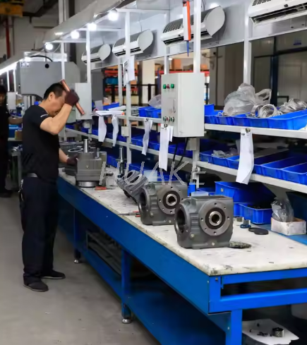
Selecting the right geometry requires looking beyond the gearbox itself. You must evaluate the surrounding machine environment. The physical constraints of your facility dictate your final choice.
Modern machine layouts prioritize density. You need a clear decision framework for choosing between wall-mounted and floor-mounted setups. If you integrate an inline helical gear motor into a dense packaging line, floor space might be unavailable. M5 or M6 positions allow you to tuck the unit against the machine frame. However, you must measure the clearance around the cooling fins. Placing the unit too close to a wall blocks ventilation. This causes rapid overheating.
Mounting angles interact directly with mechanical forces. Overhung loads (OHL) occur when pulleys or sprockets attach to the output shaft. Gravity compounds these forces depending on the mounting position. In an M1 setup, the foundation absorbs most downward forces. In an M5 wall mount, gravity creates a cantilever effect on the housing bolts. Thrust loads on the output shaft also change direction. You must recalculate your safety factors based on the specific mounting angle.
Robotic cells demand high precision and compact profiles. When utilizing an automation helical gear motor, you face strict integration challenges. Evaluate how rigid, non-standard angles impact cable routing. Power and encoder cables must bend safely without chafing. Furthermore, consider maintenance accessibility. If you bury a vertical motor inside a robotic arm casing, technicians cannot reach it. They will struggle to check oil levels or replace seals.
Your chosen orientation must meet regional safety standards. Rotating equipment requires proper guarding. If you specify an M3 ceiling mount, ensure the exposed shafts remain covered. Fluid containment also matters. Non-horizontal mounts carry a higher risk of seal leakage. You should install drip trays or secondary containment measures below vertical and wall-mounted units. This prevents oil from creating slip hazards on the factory floor.
Theoretical planning often clashes with factory floor realities. Installation crews frequently make assumptions. These assumptions can destroy expensive equipment within hours of startup.
Many buyers purchase off-theshelf M1 units. They intend to use them horizontally. Later, the design changes. The installation crew decides to rotate the unit into an M4 vertical position. They bolt it down and turn it on.
This "field modification" guarantees rapid failure. The factory shipped the unit with oil volumes calibrated for M1. The breather and drain plugs sit in M1 positions. By rotating it, the crew submerged the breather and starved the top bearings. Never reposition a factory-set reducer without consulting the manual. You must physically relocate all plugs. You must strictly adjust the oil volume. Ignoring this rule instantly voids manufacturer warranties.
A machine only survives if technicians can maintain it. Assess your chosen mounting position from a human perspective. Does it leave the oil level indicator accessible? Can mechanics clearly read the sight glass?
If they cannot reach the sight glass, they will not maintain it. Hidden units suffer from chronic neglect. Design your layouts to keep maintenance points highly visible.
Non-horizontal mounts require stricter alignment tolerances. When you suspend a heavy unit from the ceiling (M3), you change its resonant frequency. The structural frame must possess high rigidity. Weak frames allow the unit to vibrate excessively.
Vibration causes base shear. It loosens mounting bolts over time. You need robust vibration dampening for wall and ceiling setups. Use high-tensile hardware. Ensure the base plates are perfectly flat. Poor alignment in non-standard positions destroys internal gears much faster than in standard M1 setups.
Clear communication with your supplier prevents costly mistakes. You must provide them with a comprehensive picture of your application. Generic orders lead to generic, failure-prone deliveries.
Do not just send torque requirements. Build a strict checklist for your procurement team. Present the following exact requirements to your vendor:
You can identify trustworthy suppliers by their technical responses. Weak vendors will just accept the order. They will ship a generic M1 unit and hope for the best. Excellent vendors will pause the process. They will supply specific technical drawings for the requested mounting position.
They will provide updated oil volume charts. They will highlight exactly where the breather and drain plugs will sit. If a vendor cannot provide documentation tailored to your specific mounting code, find another supplier. Precision matters.
Consider the physical design of the housing. Some gearboxes feature cast-in-one-piece housings. These are rigid but inflexible. If your plant layout changes, you cannot easily adapt them to new mounting angles.
Assess modular gearbox designs instead. Modular units allow for flexible mounting plates. You can attach different bolt-on feet or flanges depending on the required position. Modular designs lower your inventory risk. You can stock a few core modules and adapt them as your factory evolves.
Mounting position represents a fundamental performance variable. It is never an aesthetic choice. Gravity relentless acts upon internal fluids and shafts. You must respect mechanical physics when integrating drive systems into your facility.
Success requires aligning mechanical loads, lubrication dynamics, and facility space limitations. Standard horizontal setups offer simplicity. Vertical and inverted setups solve space constraints but demand rigorous lubrication modifications. The standardized M1 through M6 codes provide the blueprint for this alignment.
Take immediate action on your next project. Before you issue a purchase order, consult with technical sales engineers. Review the 3D CAD models together. Confirm the exact M1-M6 designation. Ensure the factory prep-calibrates the oil levels and breather locations. This diligence guarantees a safe, reliable, and long-lasting installation.
A: Yes, but it requires manually reconfiguring the breather, drain, and level plugs. You must strictly adjust the oil volume to the manufacturer's specification for the new position. Failure to do so voids warranties and causes rapid mechanical failure.
A: Gravity pulls oil away from the upper bearings and gears. Higher oil volumes, specialized grease packing, or forced lubrication systems are required. These ensure those upper components do not run dry and seize during operation.
A: Orientations that trap heat against a wall or floor reduce the unit's thermal capacity. Blocking airflow over the cooling fins prevents heat dissipation. This situation potentially requires derating the motor or installing active cooling mechanisms to prevent overheating.


