
- All
- Product Name
- Product Keyword
- Product Model
- Product Summary
- Product Description
- Multi Field Search


Views: 0 Author: Site Editor Publish Time: 2026-08-03 Origin: Site


High-load systems place serious demands on transmission equipment. Heavy conveyors, mixers, crushers, mining machinery, rubber equipment, chemical processing machines and material handling systems often require stable torque transmission under difficult conditions. These machines may carry large loads, start under resistance, face shock loads, run for long hours or operate in dusty, humid or high-temperature environments.
In these applications, selecting the right helical gear reducer is not only about choosing a reducer with the correct speed ratio. The reducer must also handle output torque, shock load, bearing load, thermal stress, lubrication pressure, housing rigidity and long-term mechanical wear.
If the reducer is undersized, the equipment may suffer from overheating, gear tooth wear, bearing fatigue, oil leakage, vibration, shaft damage or unexpected downtime. For high-load systems, a small selection error can become a major production problem.
For high-load industrial equipment, HUAKE’s Helical Gear Reducers provide efficient and durable transmission solutions for different torque requirements, installation layouts and working environments.
This guide explains how to select a helical gear reducer for high-load systems and what factors should be checked before final model selection.
A helical gear reducer can support high-load systems when it is correctly selected according to output torque, shock load, service factor, gear ratio, bearing capacity, housing strength, lubrication and working environment.
Key points include:
High-load systems are not defined only by heavy weight.
Starting torque, shock load, variable load and continuous duty also affect reducer selection.
Helical gears provide smooth engagement and efficient torque transmission.
Hardened gear teeth help improve wear resistance under repeated loading.
Bearing and shaft support are critical for radial, axial and overhung loads.
Housing rigidity helps maintain gear alignment under heavy force.
Lubrication and cooling affect long-term reliability.
Service factor must be considered for high-load and heavy-duty applications.
Final selection should be based on real working conditions, not only motor power or gear ratio.
In short, high-load reducer selection requires a complete review of torque, load behavior, installation and environment.
A high-load system is any machine or transmission system where the reducer must handle heavy torque demand, large starting resistance, shock load, continuous operating stress or severe working conditions.
High load does not always mean the machine is physically large. A compact machine can also create high load if it has high starting torque, sudden load changes or harsh operating conditions.
| High-Load Condition | Meaning |
|---|---|
| High static load | The equipment carries or moves heavy material |
| High starting torque | The machine needs strong torque when starting |
| Shock load | Load changes suddenly or impacts the reducer |
| Variable load | Material amount, viscosity or resistance changes |
| Continuous load | The reducer runs for long hours with heat buildup |
| Overhung load | The output shaft carries strong radial force |
| Harsh environment | Dust, humidity, high temperature or corrosion affects operation |
Understanding the type of load is the first step in selecting the right heavy-duty gear reducer.
High-load systems create more mechanical stress than standard applications. The reducer must withstand repeated force while maintaining stable output speed and torque.
Output torque is one of the most important selection factors. A high-load system may require much more torque than a standard conveyor or light-duty machine. If the reducer cannot provide enough rated torque, gear teeth and shafts may be overloaded.
Some applications create sudden torque peaks. Crushers may experience impact when hard materials enter the machine. Mixers may need high torque when starting under full material load. Conveyors may start with heavy material already on the belt.
These conditions require a reducer with enough torque margin and service factor.
Many high-load systems also run for long shifts or continuous production. Long operating hours increase heat generation and lubrication stress. Gear reducer selection should therefore include thermal behavior and maintenance planning.
High-load systems often create strong radial and axial forces. If bearing capacity or shaft strength is insufficient, the reducer may face vibration, misalignment or bearing fatigue.
Heavy loads create more friction, heat and oil stress. Lubricant must maintain an effective oil film between gear teeth and bearings. Poor lubrication can quickly reduce reducer life.
A helical gear reducer is widely used in industrial transmission because it provides smooth meshing, high efficiency and strong torque transmission. These features are valuable in high-load systems.
Helical gears have angled teeth. Instead of engaging suddenly across the full tooth width, they engage gradually. This reduces impact and supports smoother operation under load.
Helical gear teeth can distribute load more smoothly across the gear mesh. This helps reduce localized tooth stress and supports more stable torque transmission.
High efficiency is important in high-load systems because energy loss becomes heat. A more efficient reducer can help reduce unnecessary heat buildup and improve power transmission.
Heavy equipment can create vibration. Smooth helical gear engagement helps reduce vibration and noise, which can protect bearings, shafts, seals and connected components.
For heavy-duty applications, hardened gear teeth and accurate gear profiles are important. They help improve wear resistance and support long-term operation under repeated load.
Application Load
        ↓
Output Torque Requirement
        ↓
Shock Load and Starting Load Check
        ↓
Service Factor Selection
        ↓
Gear Ratio and Output Speed
        ↓
Bearing, Shaft and Housing Review
        ↓
Lubrication and Thermal Check
        ↓
Final Helical Gear Reducer Model
This flow shows that high-load reducer selection should not begin and end with gear ratio. Ratio is important, but the full load condition must be reviewed before choosing the final model.
Output torque is the foundation of gear reducer selection. The reducer must provide enough torque for normal operation and peak load conditions.
When checking output torque, consider:
Normal running torque
Starting torque
Peak torque
Load fluctuation
Overload condition
Future capacity expansion
A reducer with insufficient torque capacity may overheat, wear quickly or fail under load.
Service factor is not just a safety margin. It reflects operating hours, starts and stops, shock load, duty cycle and application severity.
For high-load systems, service factor should be checked carefully. A machine with steady load may require a different margin than a crusher, mixer or mining conveyor with frequent shock load.
Shock load occurs when torque rises suddenly. This can happen during material impact, machine blockage, sudden startup, emergency stop or uneven feeding.
Applications with shock load need a reducer with stronger torque reserve, reliable bearings and durable gear tooth design.
Gear ratio affects output speed and torque. A higher ratio can reduce speed and increase torque, but it may also affect reducer size, efficiency and heat generation.
If you are still confirming speed and torque matching, this guide on gear ratio for a helical gear reducer can help you understand how ratio affects output speed and torque.
Bearings support shafts and maintain gear alignment. High-load systems may create strong radial load, axial load or overhung load.
Since helical gears generate axial thrust, bearing design is especially important. The reducer should have suitable bearing capacity for the actual load direction.
The housing supports gears, shafts and bearings. Under high load, weak housing structure may deform or allow misalignment. A rigid housing helps maintain correct gear contact and reduce internal stress.
High-load operation increases heat and lubrication demand. The oil must maintain a stable film under pressure and temperature.
Check lubricant type, oil level, oil change interval and cooling requirements. In some heavy-duty applications, additional cooling may be required.
Mounting position affects oil distribution, installation space, shaft direction and load direction. Horizontal, vertical, flange-mounted and shaft-mounted installations may require different reducer configurations.
Dust, water, humidity, chemicals, outdoor exposure and high ambient temperature can affect seals, lubricant and reducer life. Environmental conditions should be included in selection.
| High-Load Condition | Selection Focus |
|---|---|
| High static load | Output torque and gear tooth strength |
| High starting torque | Motor power and startup torque margin |
| Shock load | Service factor and overload capacity |
| Variable load | Torque reserve and load stability |
| Continuous load | Lubrication and thermal management |
| Overhung load | Bearing capacity and shaft support |
| Harsh environment | Sealing, housing strength and lubricant selection |
| High temperature | Cooling capacity and oil viscosity |
| Dust or moisture | Seal design and maintenance interval |
| Risk | Reducer Design Response |
|---|---|
| Gear tooth wear | Hardened gear teeth and accurate tooth profile |
| Bearing fatigue | Proper bearing selection and shaft support |
| Housing deformation | Rigid cast iron or heavy-duty housing |
| Overheating | High efficiency, ventilation and cooling design |
| Oil film breakdown | Correct lubricant viscosity and oil level |
| Shock damage | Service factor and overload margin |
| Shaft misalignment | Strong housing and accurate assembly |
| Contamination | Reliable seals and maintenance checks |
| Noise and vibration | Smooth helical gear engagement |
Heavy conveyor systems are used in mining, cement, bulk material handling, ports, grain processing and manufacturing lines. These systems often carry large material weight and may start under load.
For heavy conveyor systems and parallel shaft transmission layouts, the F Series Parallel Shaft Helical Gear Reducer can be considered when high torque, compact installation and stable long-term operation are required.
Mixers and agitators often face variable load. Material viscosity, filling level and blade resistance can change during operation. Startup torque may also be high when the tank is full.
Reducer selection should focus on torque reserve, bearing support and service factor.
Crushers, feeders, screens and mining equipment may experience impact load, dust and heavy torque demand. These applications require strong housing, reliable sealing, high service factor and proper lubrication.
Rubber and plastic machinery such as extruders and calenders may require high torque and long operating hours. The reducer must manage heat, gear tooth stress and lubrication stability.
Chemical mixers, reactors and processing equipment may run continuously under variable load. Users should also consider corrosion risk, sealing performance and lubricant compatibility.
Lifting and heavy material handling systems require careful torque and braking analysis. Reducer selection should consider safety margin, shock load, load holding requirements and mounting layout.
| Application | Load Feature | Reducer Selection Focus |
|---|---|---|
| Heavy conveyor | Steady load and starting torque | Torque, ratio, service factor |
| Mixer | Variable viscosity and shock load | Torque reserve and bearing support |
| Crusher | High impact and overload risk | Heavy-duty housing and service factor |
| Mining equipment | Harsh environment and high load | Seals, housing, lubrication |
| Chemical machinery | Continuous load and corrosion risk | Sealing and lubricant compatibility |
| Rubber machinery | High torque and long operation | Thermal control and gear strength |
| Lifting system | Load holding and safety demand | Torque margin and system safety |
| Material handling | Repeated start-stop load | Service factor and mounting layout |
Different high-load systems require different reducer structures. HUAKE provides multiple helical gear reducer series to support different transmission layouts and load conditions.
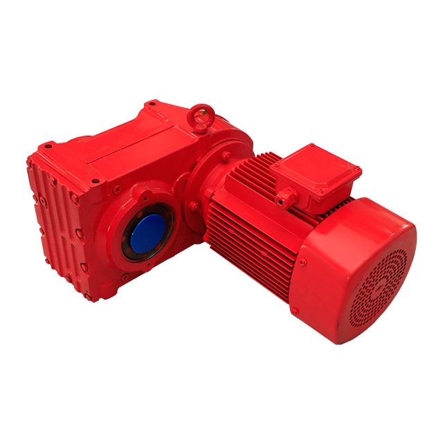
The F Series is suitable for parallel shaft layouts where compact installation, stable torque transmission and high-load capability are required. It is commonly considered for conveyors, material handling equipment and industrial production lines.
For higher-power industrial machinery, mining equipment, metallurgical systems and harsh working conditions, the H&B Series High Power Reducer provides a stronger direction for heavy-duty reducer selection.
The R Series is often suitable for inline or coaxial transmission layouts. It can be considered for general industrial machines that require compact structure, stable transmission and reliable torque output.
Some high-load systems require special mounting, non-standard shafts, special sealing, special ratio or environmental protection. In these cases, a customized reducer solution may be more suitable than a standard model.
| Requirement | Recommended Direction |
|---|---|
| Parallel shaft high-load conveyor | F Series Parallel Shaft Helical Gear Reducer |
| High-power industrial system | H&B Series High Power Reducer |
| Inline compact torque transmission | R Series Helical Gear Hardened Gear Reducer |
| Special installation or non-standard load | Customized reducer solution |
| Heavy-duty continuous operation | Confirm service factor and thermal capacity |
| Harsh outdoor environment | Check sealing, housing and lubrication design |
| Variable load and shock load | Select enough torque reserve and service factor |
High-load reducer failures are often caused by incomplete selection rather than product type alone. Common mistakes include:
Selecting only by motor power
Ignoring actual output torque
Using an insufficient service factor
Ignoring shock load or startup load
Choosing ratio without checking torque capacity
Ignoring bearing and shaft load
Ignoring mounting position
Overlooking lubrication and cooling
Ignoring dust, humidity or high temperature
Not considering maintenance access
Not planning for future load increase
Avoiding these mistakes can improve reducer reliability and reduce downtime risk.
| Selection Factor | What to Check |
|---|---|
| Motor power | Rated power and actual working load |
| Input speed | Motor rpm and reducer input rating |
| Output speed | Required machine operating speed |
| Output torque | Normal torque and peak torque |
| Gear ratio | Speed reduction and torque relationship |
| Service factor | Duty cycle, shock load and starts/stops |
| Load type | Static, variable, shock or continuous load |
| Bearing load | Radial, axial and overhung load |
| Mounting position | Horizontal, vertical, flange or shaft-mounted |
| Housing strength | Rigidity under high torque |
| Lubrication | Oil type, oil level and maintenance interval |
| Cooling | Natural cooling or additional cooling |
| Environment | Dust, humidity, temperature and chemicals |
| Maintenance access | Inspection, oil change and seal replacement |
| Expansion plan | Future load, speed or capacity increase |
HUAKE provides helical gear reducer solutions for industrial transmission systems. For high-load applications, HUAKE can help users evaluate reducer selection based on torque demand, gear ratio, service factor, shock load, motor power, mounting position, duty cycle and working environment.
HUAKE helical gear reducer solutions can support:
Heavy conveyor systems
Mining equipment
Crushers and feeders
Mixers and agitators
Chemical processing equipment
Rubber and plastic machinery
Material handling systems
Metallurgical equipment
Industrial production lines
Customized transmission layouts
A suitable reducer should not only fit the required ratio. It should also provide enough torque capacity, shock resistance, bearing support, housing rigidity, lubrication stability and thermal performance.
Selecting a helical gear reducer for high-load systems requires more than matching motor power and output speed. High-load applications may involve heavy static load, high starting torque, shock load, variable load, continuous operation, overhung load and harsh working environments.
A properly selected helical gearbox can support high-load transmission through smooth gear engagement, efficient torque delivery, hardened gear teeth, strong bearing support, rigid housing, proper lubrication and suitable thermal management. However, these advantages only work when the reducer is correctly matched to the real operating conditions.
Before choosing a reducer, users should evaluate output torque, gear ratio, service factor, shock load, load direction, mounting position, lubrication, cooling, sealing, ambient temperature and maintenance access.
Need help selecting a reducer for high-load operation? Contact HUAKE for a high-load helical gear reducer solution based on your torque, ratio, motor power, shock load, mounting position, duty cycle and operating environment.
A high-load system is a machine or transmission system that requires high torque, carries heavy material, starts under resistance, handles shock load or operates continuously under demanding conditions.
Yes. A properly selected helical gear reducer can support high-load systems because it provides smooth gear engagement, efficient torque transmission and strong load distribution.
Output torque is one of the most important factors. However, service factor, shock load, gear ratio, bearing load, lubrication and environment must also be checked.
Service factor reflects operating hours, shock load, starts and stops, duty cycle and application severity. It helps ensure the reducer has enough margin for real working conditions.
A helical gear reducer can handle shock load when properly selected with enough torque reserve, service factor, bearing capacity and durable gear design.
An undersized reducer may overheat, wear quickly, damage bearings, create vibration, leak oil or fail unexpectedly under load.
Common applications include heavy conveyors, mixers, crushers, mining equipment, chemical machinery, rubber machinery, plastic machinery, lifting systems and material handling equipment.
Lubrication protects gear teeth and bearings, reduces friction, carries heat and prevents wear. Poor lubrication can quickly shorten reducer life in high-load operation.
Both must be checked together. Gear ratio determines output speed, while torque determines whether the reducer can drive the load safely. A correct ratio is not enough if torque capacity is insufficient.
Yes. HUAKE can help evaluate motor power, input speed, output speed, torque, service factor, shock load, mounting position and working environment to recommend a suitable helical gear reducer.


