
- All
- Product Name
- Product Keyword
- Product Model
- Product Summary
- Product Description
- Multi Field Search


Views: 0 Author: Site Editor Publish Time: 2026-10-14 Origin: Site


Many engineers, hardware hobbyists, and procurement specialists confuse these two distinct components during the initial design phase of a project. Assuming they are completely interchangeable is a critical oversight. This mistake frequently causes costly equipment failures, delayed production timelines, and burnt-out control circuitry. To set the record straight, they are fundamentally different machines designed for entirely different mechanical purposes.
A standard electrical drive provides rapid, low-resistance rotation. Integrating a mechanical gearbox, however, completely transforms that high-speed velocity into sheer pushing, pulling, or lifting power. In this comprehensive engineering guide, we will explore a detailed technical comparison, examine real-world applications, and help you select the exact drive mechanism for your specific automation challenge.
To properly evaluate these components, you first need to understand the foundational technology behind them. A bare direct current drive is an electrical machine designed to convert electrical energy directly into mechanical kinetic energy.
The operation of this component relies heavily on the fundamental principles of electromagnetism. The internal structure consists of two primary parts. The stator is the stationary outer housing that generates a constant magnetic field. The rotor is the spinning armature inside. When direct current flows through the armature copper windings, it induces an electromagnetic field. This newly created field instantly interacts with the stator magnets, generating a repulsive force that compels the rotor to spin rapidly.
The most defining characteristic of a bare DC Motor is its raw operational output. These units are engineered to spin at blistering speeds, often ranging anywhere from 3,000 to over 10,000 revolutions per minute. Yet, because they lack any form of mechanical leverage, the rotational force is inherently minimal. If you attempt to pinch the spinning shaft of a small 12-volt bare motor with your fingers, you can usually stop it with very little effort.
Evaluating a standard drive requires looking objectively at its physical properties and operational limits.
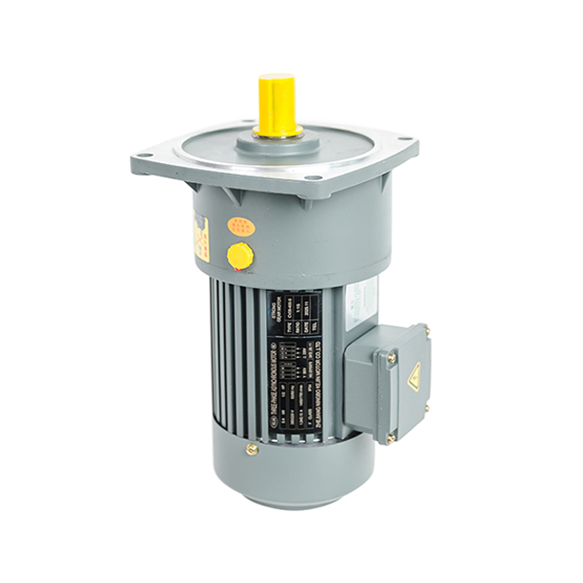
When an application demands substantial pushing force or the ability to lift a heavy payload against gravity, a high-speed bare unit is completely insufficient on its own. Engineers resolve this limitation through mechanical intervention. Specifically, they attach a specialized gearbox.
A Geared Motor is essentially a standard electric unit that has been directly coupled to a gear train. The primary function of this attached housing is to act as a mechanical speed reducer.
In physics, mechanical power is the product of speed and torque. By utilizing a series of interlocking gears with varying numbers of teeth, the gearbox intentionally reduces the high velocity of the internal shaft. In doing so, it proportionally multiplies the torque. For instance, if you take a unit spinning at 5,000 revolutions per minute and fit it with a 100-to-1 reduction gearbox, the final output shaft will turn at a highly controlled 50 revolutions per minute. However, it will possess nearly 100 times the original turning force, minus minor losses attributed to internal friction.
The integration of a gear train fundamentally alters what the machine can achieve. This offers several distinct advantages for complex engineering builds.
The most prominent benefit is the massive increase in torque capacity. This allows machinery to drive heavy conveyor belts or lift substantial weights safely. Slower rotational speeds also translate to highly accurate motion control. This accuracy is critical for robotic arms trying to position components within millimeters. Furthermore, certain gearbox designs cannot be driven backward by the load. This creates a natural self-locking brake that drastically enhances safety in vertical lifting applications.
When placing these two systems side by side, technical buyers must analyze several dimensions. The addition of a mechanical gear train changes the performance metrics, the physical footprint, and the acoustic profile of the unit.
| Feature | Standard Bare Motor | Geared Assembly |
|---|---|---|
| Rotational Speed | Extremely high. Typically 3,000 to 10,000+ revolutions per minute. | Low and controlled. Typically 10 to 500 revolutions per minute. |
| Torque Output | Very low. Easily stalled by physical resistance. | Exceptionally high. Capable of moving heavy industrial payloads. |
| Physical Footprint | Compact and lightweight. Fits easily into small enclosures. | Bulkier and heavier due to the metal gear train and lubrication housing. |
| Acoustic Profile | High-pitched whine caused by rapid rotor spinning. | Lower-frequency mechanical grinding or meshing noise under load. |
| Primary Use Case | Fans, pumps, blowers, and lightweight consumer electronics. | Conveyor belts, robotic arms, smart home gates, and lifting hoists. |
The most critical distinction lies in the inverse relationship between velocity and force. A standard drive prioritizes speed, making it ideal for continuous, unimpeded motion like spinning a fan blade. Conversely, a geared setup prioritizes brute force. If your project involves opening a heavy steel gate, a bare unit will simply stall and emit the dreaded smell of burning enamel. A geared unit, however, will turn slowly and push the gate open with steady authority.
Not all gearboxes are engineered using the same internal geometry. The arrangement of the gears dictates the load capacity, spatial footprint, and overall lifespan. Understanding these variations is crucial for selecting the correct Gear Motor for your specific production line.
Planetary systems feature a central sun gear surrounded by multiple rotating planet gears. These are all tightly enclosed within an outer ring gear. Because the mechanical stress is distributed evenly across multiple contact points simultaneously, these units resist wear incredibly well.
They offer the highest torque density and efficiency available in a compact, inline footprint. Engineers frequently specify planetary designs for high-precision aerospace components, advanced robotics, and scenarios where maximum power must fit into a highly restricted space.
Worm gearboxes utilize a unique right-angle configuration. A screw-like gear meshes perpendicularly with a standard toothed wheel. This geometry provides massive speed reduction in a single stage.
Most notably, worm gears boast an inherent self-locking mechanism. The worm can easily turn the wheel, but the wheel cannot force the worm to turn backward. This acts as an automatic safety brake. It makes them the industry standard for hoisting equipment, passenger elevators, and automated security gates.
Spur gears represent the most traditional speed reducer design. They utilize straight-cut gears mounted on parallel shafts. They are highly cost-effective and straightforward to manufacture.
However, the physical load is concentrated on just one or two gear teeth at any given moment. Therefore, they handle significantly lower torque limits compared to planetary designs. They also tend to generate more vibration and noise. This makes them better suited for budget-conscious projects like automated window blinds or light-duty smart home devices.
Selecting the correct drive setup is a rigorous, exact science. Guessing specifications based on visual size often leads to stripped gears or sluggish machinery. Following a structured evaluation process ensures long-term system reliability.
The foundation of component selection begins with empirical math. You must determine the exact physical force required to move your load and the speed at which it needs to travel. Once you calculate your target velocity and required torque, you can cross-reference this with a manufacturer specification sheet.
Take a standard 42-millimeter planetary gearbox assembly as a practical example. You might feed it 24 volts to run the internal rotor at 4,000 revolutions per minute. By applying a 100-to-1 reduction ratio, the output shaft turns at a highly controlled 40 revolutions per minute while delivering an impressive 30 Newton-meters of torque. Always factor in a safety margin of at least 20 percent. Running a machine constantly at its absolute peak stall torque will drastically shorten its operational lifespan.
Mechanical specifications only solve half the puzzle. The physical environment dictates the rest. If your machine internal housing is long and narrow, an inline planetary gearbox is ideal. If depth is severely restricted, a right-angle worm gearbox allows the main body to be tucked away perpendicularly.
Additionally, consider the operating climate. Industrial environments filled with airborne dust, corrosive moisture, or extreme heat require sealed gearboxes. Look for strict Ingress Protection ratings and specialized thermal lubricants to prevent mechanical lockup.
Even with precise calculations, integrating a bare unit with a separate gearbox introduces severe alignment risks. Misalignment by a fraction of a millimeter causes intense vibration and rapid bearing failure. Therefore, sourcing a pre-assembled Industrial Motor from a reputable manufacturer is highly recommended.
Working directly with established suppliers allows technical buyers to access customizable solutions tailored to exact load profiles. This ensures the final unit performs flawlessly under specific duty cycles.
Looking at recent market analyses and engineering discussions regarding automation design, a clear industry trend emerges. Historically, equipment designers would purchase bare electrical components and manually attach third-party gearboxes, hoping the coupling would hold up under stress. Today, the manufacturing sector is leaning heavily toward highly integrated, pre-assembled drive units.
The relentless demand for miniaturization in logistics robotics and smart home appliances means that modern speed reducers must deliver unprecedented torque density in an increasingly smaller footprint. Furthermore, as Internet of Things architecture becomes standard across factory floors, the line between simple mechanical actuation and intelligent, sensor-driven control is blurring. Buyers no longer just want a spinning shaft. They demand complete, plug-and-play motion solutions that guarantee exact repeatability, lower acoustic profiles, and zero maintenance overhead. The ability to monitor gear wear and thermal output in real-time is rapidly becoming a baseline expectation rather than a premium feature.
Examining real-world deployment clarifies exactly why engineers choose one setup over another. The choice ultimately boils down to whether the end-use application prioritizes pure velocity or deliberate force.
Because they excel at generating rapid rotation with minimal drag, bare units dominate applications where moving air, fluids, or lightweight mechanisms is the primary goal.
Whenever controlled, deliberate force is required to manipulate the physical environment against gravity or friction, a gearbox is absolutely necessary.
Even premium-grade components will fail catastrophically if subjected to improper operational conditions. Technicians frequently encounter premature equipment breakdowns due to two primary oversights.
The most common point of failure in a geared assembly is not the electrical winding, but the mechanical teeth. Every gearbox has a maximum rated torque limit. If a conveyor belt jams, the electrical stator will continue applying rotational force against the stalled gears. This creates immense shear stress. It frequently results in stripped gears where the metal teeth are physically sheared off the wheel. Implementing current-limiting power supplies or mechanical slip clutches is vital for preventing this exact scenario.
A duty cycle represents the percentage of time a machine can safely operate under full load before it requires a cooling period. Because internal gears generate continuous friction, geared units naturally produce more heat than bare units.
Running a unit continuously beyond its rated duty cycle leads to thermal overload. This excessive heat breaks down synthetic lubricants, melts the protective enamel on the copper coils, and ultimately causes a dead electrical short. Always match the duty cycle rating to the actual demands of your production environment.
While they may share the same foundational electrical principles, standard drives and geared assemblies serve entirely different engineering purposes. A basic electrical unit provides blistering speed for low-resistance tasks. The addition of a mechanical gearbox sacrifices that speed to generate massive, highly controlled torque.
Understanding this inverse relationship is the key to successful machine design. Before finalizing any purchase, rigorously calculate your specific torque requirements, evaluate your spatial constraints, and respect the duty cycle limits of the equipment. Stop guessing with your motion control designs. If you need reliable, high-torque solutions tailored to your exact specifications, explore the full range of drive systems at Huake Gearbox. Match your empirical data with proven industrial solutions to keep your production lines moving safely and efficiently.
Yes, it is technically possible to retrofit a bare unit with a separate gearbox. However, it requires flawless mechanical alignment. If the shaft and the gearbox input are misaligned by even a fraction of a millimeter, it will cause severe vibration, increased friction, and rapid bearing failure. For commercial and industrial applications, buying a pre-assembled unit straight from the manufacturer is strongly recommended to ensure proper sealing and optimal efficiency.
A geared setup is absolutely necessary for an industrial conveyor system. Conveyors require massive amounts of torque to pull heavy, continuous loads at a slow, deliberate pace. A standard bare unit lacks the turning force to move such weight. It would immediately stall, overheat, and burn out. Utilizing a speed reducer provides the exact low-speed, high-torque output required for safe material handling.
Electrical consumption depends entirely on the mechanical load being moved. Because the internal electrical components are identical, they draw similar baseline power. However, internal gears introduce friction, resulting in a slight efficiency loss. Therefore, in a zero-load scenario, a geared unit draws marginally more power. But under a heavy payload, a geared unit is far more efficient. A bare unit would stall and draw massive, damaging current spikes trying to move a weight it cannot handle.
It depends entirely on the manufacturer duty cycle rating and the thermal dissipation of the environment. Some heavy-duty industrial units are designed for 24/7 continuous operation and feature advanced cooling fins and high-temperature synthetic lubricants. However, standard commercial units often have intermittent duty cycles. Running a light-duty unit continuously will cause thermal overload and destroy the internal gear lubrication.
The choice between 12-volt and 24-volt systems usually comes down to your available power supply and current limitations. A 24-volt system will draw half the current of a 12-volt system to produce the exact same mechanical power. Lower current means you can use thinner wiring and smaller motor controllers, which reduces heat generation. If you are building a heavy-duty robotic platform or industrial machine, 24-volt is generally preferred for its electrical efficiency.


