
- All
- Product Name
- Product Keyword
- Product Model
- Product Summary
- Product Description
- Multi Field Search


Views: 0 Author: Site Editor Publish Time: 2026-06-19 Origin: Site


Engineers and system integrators rarely choose planetary gearboxes by default. Higher initial costs usually push them toward standard alternatives first. They only make this shift when strict operational constraints demand specific performance thresholds. Coaxial load distribution among planet gears directly solves three distinct mechanical problems. It maximizes torque density, dramatically improves torsional stiffness, and bypasses severe radial space limitations. This guide outlines specific industrial and precision scenarios requiring these advanced solutions. You will discover why Planetary Gear Reducers are often an engineering requirement rather than merely an option. We also provide a clear framework for evaluating them properly for your next demanding project.
Planetary gear reducers are mandatory for applications requiring high torque density within a compact, coaxial footprint.
They dominate servo-driven motion control, robotics, and heavy material handling where low backlash and high torsional stiffness are critical.
Choosing an Industrial Planetary Gear Reducer requires balancing acceleration torque against thermal limitations and duty cycles.
Over-speccing can lead to unnecessary thermal issues and bloated project costs; precise load profiling is the foundation of a successful specification.
Moving away from standard spur, helical, or worm gears requires specific decision criteria. You do not abandon simple gear sets without a compelling technical reason. Standard parallel-shaft reducers take up considerable radial space. Worm gears lose energy to friction and wear out quickly. We see engineers shift toward a planetary design when they face a necessity threshold.
Three specific triggers mandate this architectural change:
Space-to-Torque Ratio: The application demands maximum output torque. However, you lack the radial space necessary for a bulky parallel shaft reducer.
Reversibility and Precision: Rapid, high-frequency start-stop-reverse cycles occur constantly. These aggressive profiles require minimal backlash, often below three arc-minutes.
Coaxial Alignment: The drive motor and the driven load must remain on the exact same axis. This simplifies overall machine design and eliminates offset mounting brackets.
Engineers frequently compare planetary units against harmonic drives or worm gears. It helps to review a skeptical, transparent comparison chart before making structural choices.
| Gear Technology | Torque Limit | Backlash Capability | Operating Efficiency |
|---|---|---|---|
| Planetary Drive | Very High | Low (< 3 arc-minutes) | High (95-97% per stage) |
| Harmonic Drive | Low to Medium | Zero Backlash | Medium (approx. 70-80%) |
| Worm Gear | Medium | High (increases over time) | Low (prone to wear and friction) |
Harmonic drives offer zero backlash. They excel in pure positioning but suffer from lower torque limits. Worm gears cost significantly less upfront. However, they remain highly inefficient and are heavily prone to rapid tooth wear.
Servo-driven systems rely heavily on planetary architecture. You rarely see complex motion control executed using standard helical gearboxes. High-speed automation demands rapid acceleration and precise stopping.
Delta and SCARA robots represent perfect examples of this necessity. These fast-moving robotic arms require a high dynamic response. They also demand extremely low inertia and high torsional stiffness. If a gearbox flexes under load, you experience settling time delays. The arm literally vibrates at the end of its stroke before settling into position. A rigid planetary design prevents this costly delay.
CNC machining centers face similar precision requirements. They must maintain continuous precision under varying tool loads. When a cutting tool hits harder material, it creates sudden resistance. The gearbox must hold the axis firm against these micro-shocks.
Engineers must evaluate more than just nominal backlash in these applications. They must deeply analyze torsional stiffness and lost motion. Flexibility anywhere inside the gearbox degrades overall positioning accuracy. If the planet gears deflect slightly under load, the robotic arm misses its target coordinates.
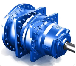
Heavy industries operate under punishing conditions. You must transition to an Industrial Planetary Gear Reducer to survive these extreme environments. Standard gears simply fail under the massive strain of bulk handling.
Consider conveyor systems and mining equipment. These machines encounter brutal shock loads daily. Load distribution across multiple planet gears handles these extreme peak torques effectively. A sudden jam on a rock conveyor would easily strip the teeth off traditional spur gears. A planetary setup spreads that violent impact across three or four internal gear meshes.
Packaging machinery relies on a different kind of heavy-duty performance. High-speed continuous packaging requires the tight synchronization of multiple moving axes. If one axis slips or lags, the entire packaging web misaligns.
Implementation reality dictates careful attention to external forces. In these high-load scenarios, you cannot only focus on the internal gear rating. Bearings face massive external pressure.
Radial Forces: High-tension belts and heavy sprockets pull forcefully on the output shaft.
Axial Forces: Helical gears inside adjoining equipment can push back against the drive.
Bearing Capacity: The gearbox bearings must handle these external loads without premature failure.
Many modern applications face extreme limitations regarding weight and volume. When space is your primary constraint, coaxial designs excel.
Automated Guided Vehicles (AGVs) and Autonomous Mobile Robots (AMRs) demonstrate this perfectly. Engineers must maximize available chassis space for battery packs. Planetary reducers fit neatly and directly into the wheel hubs of these mobile robots. This integration completely removes the drivetrain from the main vehicle body.
Aerospace and defense sectors push these volume limits even further. Radar tracking systems require rapid, precise movement to lock onto targets. Flight control actuation demands absolute reliability. Failure is simply not an option in these critical environments. Designers must relentlessly optimize power-to-weight ratios to conserve fuel and lift capacity.
You must remain transparent about design trade-offs in these constrained footprints. Minimizing weight creates distinct engineering challenges. Standard steel housings become too heavy, requiring specialized aluminum or titanium alloys. Smaller internal volumes leave less room for vital oil reservoirs. You must specify optimized, high-performance lubrication to prevent rapid overheating. These specialized material demands inherently drive up unit design constraints.
Selecting the correct unit involves more than just reading a catalog specification. Procurement and engineering teams need a reliable technical checklist to shortlist appropriate units. We recommend evaluating every application through a strict, multi-point decision framework.
| Evaluation Metric | Common Mistake | Best Practice Solution |
|---|---|---|
| Nominal Torque | Sizing solely based on running torque. | Calculate emergency stop and peak acceleration torque first. |
| Duty Cycle | Ignoring S1 (continuous) vs S5 (cyclic) thermal differences. | Map exact cycle times to assess heat dissipation needs. |
| Environment | Using standard seals in washdown areas. | Specify correct IP ratings and food-grade lubricants. |
Sizing a unit based solely on nominal torque introduces massive danger. Running torque only tells part of the story. You must meticulously calculate acceleration torque and emergency stop torque. If a heavy load jams suddenly, the gearbox absorbs an immense energy spike. Failing to calculate this peak torque leads to catastrophic mechanical failure.
You must also differentiate between continuous operation (S1) and cyclic operation (S5). Planetary gears naturally trap heat due to their incredibly compact size. They pack high power transmission into a minimal footprint. This density leaves very little surface area available for natural cooling. Thermal dissipation often becomes the primary evaluation metric for continuous S1 operations.
Environmental compliance requires equal attention. Food and beverage applications demand strict food-grade lubrication and washdown-ready IP ratings. Outdoor or chemical environments require corrosion-resistant housings to survive long-term exposure.
Implementations frequently fail during the final integration phase. Even correctly specified gearboxes will self-destruct if installed improperly. Demonstrating engineering authority requires pointing out these common integration pitfalls.
Mounting misalignment causes severe issues almost immediately. Improper motor mounting forces the input shaft slightly off-center. This introduces unintended radial loads directly onto the delicate input bearings. You will notice increased operational noise first. Premature bearing failure inevitably follows shortly after.
Lubrication starvation presents another hidden danger. Engineers sometimes specify a gearbox for horizontal use but mount it vertically. Operating at extreme angles forces oil away from the upper gear stages. You must specify the exact correct lubrication volume and select the appropriate sealing arrangement for your intended mounting orientation.
Finally, avoid the common trap of over-speccing backlash. Many engineers instinctively demand a premium one arc-minute backlash rating. However, their specific application may only realistically require five to seven arc-minutes. Tighter mechanical tolerances naturally increase internal friction. This friction generates more trapped heat and dramatically increases structural demands.
Planetary gear reducers serve a distinct, demanding role in modern engineering. They are purpose-built for applications demanding high torque density, exact coaxial alignment, and precise positioning. You should not use them as a default replacement for basic power transmission.
We advise readers to deeply map their application parameters before contacting any manufacturer. Document your exact load profile, identify your duty cycle, and measure your thermal environment constraints. This preparation ensures you request the correct internal architecture from the start.
Your next step should involve consulting directly with a qualified application engineer. We highly recommend downloading a specialized sizing tool or requesting a detailed 3D CAD model. Testing the digital model within your specific project integration helps identify footprint conflicts early.
A: They typically achieve exceptional efficiencies of 95% to 97% per gear stage. The coaxial load distribution minimizes friction compared to worm gears. However, this efficiency naturally drops when operating at very low speeds or when utilizing higher reduction ratios across multiple stages.
A: Yes, they are generally completely back-drivable. Unlike worm gears, they do not offer inherent self-locking capabilities. If you lose motor power, the load can drive the gearbox backward. You must install a dedicated brake mechanism for safety, especially in vertical lifting applications.
A: They suffer from high thermal density. They transmit massive amounts of mechanical power within a very small physical footprint. This compact design leaves significantly less outer surface area available for natural heat dissipation. Continuous duty applications often require external cooling solutions.
A: You follow a two-step rule. First, accurately match the motor's peak output torque to the gearbox's maximum allowable acceleration torque. Second, verify the inertia matching ratio. The ratio between the reflected load inertia and the motor inertia must remain within acceptable drive limits.


