
- All
- Product Name
- Product Keyword
- Product Model
- Product Summary
- Product Description
- Multi Field Search


Views: 0 Author: Site Editor Publish Time: 2026-08-05 Origin: Site


Choosing the right gear ratio is one of the most important steps when selecting a helical gear reducer. If the ratio is too low, the machine may run too fast and the output torque may be insufficient. If the ratio is too high, the equipment may run too slowly, the reducer may become larger than necessary, and the system may lose efficiency.
For industrial machinery, the correct gear ratio should not be selected by guesswork. It should be based on motor speed, required output speed, output torque, load type, service factor, mounting position, duty cycle and operating environment.
A helical gearbox is often used in conveyors, pumps, mixers, packaging machinery, food processing equipment, rubber machinery, plastic machinery and material handling systems. Each application has different speed and torque requirements. That means the best gear ratio for one machine may not be suitable for another.
For users comparing reducer speed, torque and mounting layouts, HUAKE’s Helical Gear Reducers provide multiple configurations for industrial transmission systems.
This article explains what gear ratio means, how it affects speed and torque, how to calculate a basic ratio and what to check before selecting a helical gear reducer.
The right gear ratio for a helical gear reducer depends on the required output speed, motor input speed, output torque, load type, operating hours and service factor.
Key points include:
Gear ratio controls how much the reducer lowers speed.
A higher gear ratio usually means lower output speed and higher output torque.
A lower gear ratio keeps output speed higher but provides less torque multiplication.
Gear ratio selection should begin with input speed and required output speed.
Output torque, load shock and service factor must also be checked.
The highest ratio is not always the best choice.
The reducer series, mounting layout and application environment also matter.
Final selection should be confirmed against the reducer’s rated torque and operating conditions.
In short, gear ratio is the starting point of reducer selection, not the only factor.
Gear ratio describes the relationship between the input speed and output speed of a reducer. In a helical gear reducer, the motor provides input speed, and the reducer lowers that speed while increasing usable torque at the output shaft.
A simple way to understand gear ratio is:
Gear Ratio = Motor Input Speed ÷ Required Output Speed
For example, if a motor runs at 1500 rpm and the machine needs 100 rpm at the output shaft, the basic reduction ratio is:
1500 ÷ 100 = 15
This means the application may require a ratio close to 15:1.
However, this calculation is only the starting point. The actual helical gear reducer selection must also consider torque, efficiency, load type, duty cycle, mounting position, service factor and safety margin.
Gear ratio affects two major performance factors: output speed and output torque.
A higher ratio reduces the output speed more. For example, a 30:1 ratio produces a slower output speed than a 10:1 ratio when the motor speed is the same.
This is useful when the machine requires slow and controlled movement, such as mixers, conveyors, hoists or material handling equipment.
As speed is reduced, torque is usually increased. This is why gear reducers are used when machines need more force at lower speed.
A simplified torque estimate is:
Estimated Output Torque = Motor Torque × Gear Ratio × Gearbox Efficiency
This formula is only an estimate. Actual torque capacity must be confirmed based on the reducer’s rated output torque, efficiency, service factor, load condition and manufacturer data.
A higher ratio may require more gear stages or a larger reducer. More stages can increase mechanical losses and heat generation. If the reducer is oversized or poorly matched, the system may waste energy or operate inefficiently.
Therefore, the best ratio is not the highest ratio. It is the ratio that gives the required speed and torque while maintaining efficiency, reliability and proper thermal performance.
Motor Speed
        ↓
Required Machine Output Speed
        ↓
Basic Gear Ratio Calculation
        ↓
Load Type and Torque Requirement
        ↓
Service Factor Check
        ↓
Reducer Series and Mounting Selection
        ↓
Final Helical Gear Reducer Model
This process shows why ratio selection should not stop after a simple speed calculation. A reducer that has the correct output speed may still fail if torque capacity, service factor, load shock or thermal conditions are ignored.
Gear ratio requirements vary across industries and machines. The table below provides a general selection logic, not fixed rules.
| Gear Ratio Choice | Output Speed | Output Torque | Typical Use |
|---|---|---|---|
| Lower ratio | Higher speed | Lower torque increase | Fans, light conveyors, faster movement |
| Medium ratio | Balanced speed | Balanced torque | General conveyors, pumps, packaging lines |
| Higher ratio | Lower speed | Higher torque increase | Mixers, crushers, heavy material handling |
A lower ratio may be suitable when the machine needs faster movement and the load is light. A medium ratio is often used for general industrial transmission. A higher ratio is suitable when the machine requires slower motion and greater torque.
The correct range should always be checked against actual output speed and load torque.
Different equipment types require different speed and torque characteristics. The same helical gear reducer ratio cannot be used for every machine.
Conveyor systems require a ratio that matches belt speed and load weight. If the ratio is too low, the belt may move too fast and material flow may become unstable. If the ratio is too high, the conveyor may move too slowly and reduce production capacity.
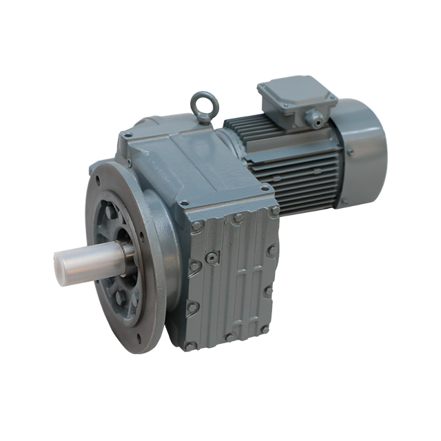
For conveyor systems and parallel shaft layouts, the F Series Parallel Shaft Helical Gear Reducer is often suitable when belt speed, torque and installation space must be balanced.
Pumps must operate within a suitable speed range. A wrong ratio may reduce flow performance, increase vibration or create unnecessary energy loss. Pump gearbox selection should consider motor speed, required pump speed, load stability and continuous operation.
Mixers usually need lower speed and higher torque. The correct ratio depends on material viscosity, mixing volume, blade design, startup torque and operating time. High-viscosity materials may require a higher torque margin.
Packaging equipment often requires smooth and synchronized motion. Ratio selection should support proper machine timing, stable speed and low vibration. Too much speed variation can affect filling, sealing, labeling or conveying accuracy.
Crushers and heavy-duty material handling equipment require high torque and strong shock load resistance. The gear ratio should be selected together with service factor and reducer strength. A ratio that provides the required speed but lacks torque margin may cause early reducer failure.
Food processing equipment may require stable speed, smooth operation and easy maintenance access. Ratio selection should also consider hygiene layout, washdown conditions, lubrication requirements and installation space.
| Application | Ratio Selection Focus | Notes |
|---|---|---|
| Conveyor systems | Match belt speed and load torque | Avoid excessive material speed |
| Pumps | Match pump speed and efficiency range | Too high a ratio may reduce process output |
| Mixers | Ensure low speed and high torque | Consider startup torque and material viscosity |
| Packaging machinery | Match synchronized machine speed | Smooth motion and positioning matter |
| Crushers | High torque and shock load margin | Service factor is critical |
| Food machinery | Stable speed and clean layout | Consider mounting and maintenance access |
| Rubber machinery | Torque and continuous operation | Check thermal capacity and lubrication |
| Chemical equipment | Stable torque and sealing | Consider environment and corrosion risk |
Incorrect gear ratio selection can create several operational problems.
If the gear ratio is too low, the output speed may be too high. This can cause poor process control, excessive machine speed, unstable material movement or insufficient output torque.
Possible results include:
Machine runs too fast
Torque is insufficient
Motor may overload
Conveyor speed becomes unstable
Product handling becomes less accurate
Starting load becomes difficult
If the gear ratio is too high, the output speed may be too low. The machine may not reach its required production speed. A very high ratio may also require a larger reducer or additional gear stages.
Possible results include:
Output speed is too slow
Production capacity is reduced
Reducer size may increase
Efficiency may decrease
Heat generation may increase
System cost may rise unnecessarily
Sometimes the ratio is correct, but the reducer is still not suitable because the output torque rating is too low. This is why ratio and torque must always be checked together.
Gear ratio is important, but it is not the only selection factor. A complete helical gear reducer selection should include the following points.
The reducer must provide enough torque under normal and peak load. Torque should be calculated based on machine load, startup conditions and service factor.
Service factor accounts for operating hours, starts and stops, load shock and application severity. Continuous-duty machines and heavy-load applications usually need a higher safety margin.
A steady conveyor load is different from a mixer, crusher or intermittent shock load. Load type directly affects reducer durability.
Mounting position affects lubrication, installation layout and output shaft direction. Horizontal, vertical, flange-mounted and shaft-mounted designs may require different reducer configurations.
A machine running one shift has different requirements from a machine operating continuously. Longer operating hours increase the importance of lubrication, heat control and bearing life.
Lubrication protects gear teeth and bearings. Thermal control prevents excessive oil temperature. These factors become especially important in high-ratio, high-torque or continuous-duty applications.
The reducer must fit the machine layout. Inline, parallel shaft and other arrangements should be selected according to installation space and power transmission direction.
For coaxial transmission layouts that require wide ratio options and compact installation, the R Series Helical Gear Hardened Gear Reducer can be considered during reducer ratio selection.
| Mistake | Possible Result |
|---|---|
| Choosing ratio only by motor speed | Torque may be insufficient |
| Choosing too low a ratio | Output speed may be too high |
| Choosing too high a ratio | Output speed may be too slow |
| Ignoring service factor | Reducer may overload |
| Ignoring efficiency | Motor power may be wasted |
| Ignoring load shock | Gear and bearing life may be reduced |
| Ignoring mounting layout | Installation may not fit the machine |
| Ignoring operating hours | Reducer may overheat in continuous duty |
| Ignoring lubrication | Gear wear may increase |
| Ignoring future load increase | Reducer capacity may become insufficient |
| Selection Factor | What to Check |
|---|---|
| Motor input speed | Motor rpm under actual operating condition |
| Required output speed | Machine shaft speed or process speed |
| Basic gear ratio | Input speed divided by output speed |
| Output torque | Required torque under normal and peak load |
| Motor power | Whether motor power matches torque demand |
| Service factor | Duty cycle, shock load and operating hours |
| Load type | Steady, variable, shock or heavy load |
| Application | Conveyor, pump, mixer, packaging line or crusher |
| Mounting position | Horizontal, vertical, flange or shaft-mounted |
| Shaft layout | Inline, parallel shaft or other layout |
| Lubrication | Oil type, oil level and maintenance interval |
| Thermal condition | Ambient temperature and heat dissipation |
| Expansion plan | Future speed, torque or production changes |
HUAKE provides helical gear reducer solutions for industrial transmission systems. Instead of selecting only by ratio, HUAKE can help users evaluate the complete working condition and recommend a suitable reducer configuration.
Selection support can include:
Motor power review
Input speed confirmation
Required output speed calculation
Output torque estimation
Gear ratio selection
Service factor evaluation
Load type analysis
Mounting position selection
Lubrication and cooling review
Application environment assessment
Reducer series matching
HUAKE helical gear reducer solutions can support conveyors, pumps, mixers, packaging machinery, food processing equipment, rubber machinery, plastic machinery, chemical equipment and heavy-duty industrial production lines.
The best reducer selection should match both the required ratio and the real working conditions of the machine.
Choosing the right gear ratio for a helical gear reducer starts with a simple question: what output speed does the machine need? From there, users can calculate a basic ratio by comparing motor input speed with required output speed.
However, gear ratio selection does not end with speed calculation. Output torque, service factor, load type, operating hours, mounting position, lubrication, thermal control and installation layout must also be considered. A ratio that looks correct on paper may still be unsuitable if the reducer cannot handle the real working conditions.
For conveyors, pumps, mixers, packaging lines, crushers and other industrial machinery, the right helical gear reducer ratio should balance speed, torque, efficiency, reliability and service life.
Need help selecting the right ratio? Contact HUAKE for a helical gear reducer selection based on your motor power, input speed, required output speed, load torque, duty cycle, shock load, mounting position and operating environment.
Gear ratio is the relationship between input speed and output speed. It shows how much the helical gear reducer reduces motor speed before delivering torque to the machine.
A basic calculation is: gear ratio equals motor input speed divided by required output speed. For example, if the motor speed is 1500 rpm and the required output speed is 100 rpm, the ratio is about 15:1.
A higher gear ratio usually increases output torque while lowering output speed. However, actual torque also depends on motor power, gearbox efficiency, service factor and reducer rating.
No. A higher gear ratio is not always better. It may make the machine too slow, increase reducer size, reduce efficiency or create unnecessary heat. The correct ratio depends on application needs.
If the ratio is too low, the output speed may be too high and the output torque may be insufficient. This can cause unstable operation or motor overload.
If the ratio is too high, the output speed may be too slow. The reducer may also become larger or less efficient than necessary.
A conveyor ratio should be selected according to belt speed, load weight, motor speed, required torque and operating hours. There is no single fixed ratio for every conveyor.
A mixer usually requires lower speed and higher torque. The ratio should be selected according to material viscosity, tank volume, blade design, startup torque and load fluctuation.
Service factor accounts for operating hours, shock load, starts and stops, and application severity. It helps ensure the reducer has enough margin for real working conditions.
Yes. HUAKE can help evaluate motor power, input speed, required output speed, output torque, gear ratio, service factor, mounting position and operating environment to recommend a suitable helical gear reducer.


