
- All
- Product Name
- Product Keyword
- Product Model
- Product Summary
- Product Description
- Multi Field Search


Views: 0 Author: Site Editor Publish Time: 2026-10-12 Origin: Site


Gear reducers are available in several mechanical designs because industrial machines do not all require the same speed, torque, shaft arrangement, efficiency, precision, or installation space. The most common types include helical, bevel, worm, planetary, cycloidal, and cylindrical gear reducers. Each design reduces motor speed and increases usable output torque, but the way the gears transmit power can be very different. Helical reducers use angled gear teeth to provide smooth and efficient transmission. Bevel reducers redirect mechanical power between intersecting shafts and are commonly used for right-angle layouts. Worm reducers use a worm and worm wheel to produce compact right-angle transmission and relatively large reduction ratios. Planetary reducers distribute torque through several planet gears around a central sun gear, providing high torque density in a compact structure. Cycloidal reducers use eccentric cycloidal motion and multiple contact points to support high ratios, shock resistance, and precision transmission. Cylindrical industrial gearboxes are generally selected for robust heavy-duty power transmission in demanding machinery. No reducer type is automatically best for every application because the correct choice depends on output speed, torque, duty cycle, efficiency, backlash, mounting, environmental conditions, and total lifecycle cost. HUAKE provides several of these gear reducer structures for applications ranging from conveyors and mixers to heavy industrial machinery, automation, and robotic joints.
Before comparing individual designs, it helps to understand the main mechanical differences between the most common gear reducers. The internal gearing determines how efficiently power is transmitted, how much torque the gearbox can handle, and how the input and output shafts are positioned. It also influences noise, backlash, heat generation, lubricant requirements, and gearbox dimensions. Helical and bevel designs are frequently chosen for continuous-duty industrial machinery because their gear engagement can provide smooth power transmission. Worm reducers are attractive where a compact right-angle layout and a relatively high ratio are priorities. Planetary reducers are common where torque density, compact dimensions, and positioning performance matter. Cycloidal reducers are often used where high reduction ratios, strong impact resistance, and low-backlash transmission are important. Cylindrical gear reducers are more common in large industrial drives where heavy loads and long service life are central requirements. Engineers should therefore compare the reducer structure against the real machine duty rather than selecting a gearbox from ratio alone. A conveyor that runs continuously for thousands of hours has different requirements from a robotic joint that repeatedly accelerates, reverses, and positions. The following comparison provides a practical starting point before examining each gear type in more detail.
| Gear Reducer Type | Shaft Layout | Main Strength | Typical Applications |
|---|---|---|---|
| Helical | Inline or parallel | Smooth, efficient transmission | Conveyors, mixers, industrial machinery |
| Bevel | Usually right-angle | Efficient directional change | Packaging, automation, material handling |
| Worm | Right-angle | Compact high-ratio reduction | General machinery, positioning systems |
| Planetary | Usually inline | High torque density | Servo systems, automation, precision machinery |
| Cycloidal | Inline / compact | High ratio, shock resistance | Robotics, automation, heavy positioning |
| Cylindrical | Parallel / industrial | Heavy-duty load capacity | Mining, metallurgy, bulk handling |
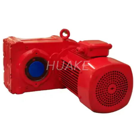
Helical gear reducers are among the most widely used industrial gearbox types because they provide a practical combination of efficiency, load capacity, smooth operation, and service life. Their gear teeth are cut at an angle rather than parallel to the shaft, which means tooth engagement occurs progressively instead of all at once. This gradual engagement helps reduce vibration and noise compared with simpler straight-tooth arrangements under similar operating conditions. Helical gearing can also maintain multiple teeth in contact during transmission, allowing loads to be shared across the gear mesh. These characteristics make helical reducers suitable for conveyors, mixers, material-handling systems, production machinery, processing equipment, and many continuous-duty applications. Inline helical reducers place the input and output shafts on or near the same axis, while parallel-shaft designs place the shafts parallel to one another. Parallel configurations are useful where the machine needs a compact drive arrangement without extending the transmission too far in the axial direction. HUAKE's F Series Parallel Shaft Helical Gearmotor is an example of this configuration for industrial power transmission. Helical gear reducers generally perform particularly well when the machine operates for long periods and transmission efficiency affects energy consumption and heat generation. They can also be combined with multiple stages when a larger overall reduction ratio is required. Engineers should still check axial loads, mounting position, bearing capacity, lubrication, and service factor because the angled teeth produce forces that must be supported correctly.
A helical reducer is usually a strong candidate when the machine requires reliable continuous transmission with moderate to high torque. It is especially useful when efficiency matters because a gearbox running around the clock can turn small transmission losses into meaningful energy costs over its operating life. Conveyors are a common application because they require stable speed and strong starting torque while often operating for long production shifts. Mixers and agitators also benefit from smooth low-speed output when the process places continuous load on the transmission. Production lines may prefer helical reducers where low vibration helps protect connected machinery and maintain stable operation. Parallel-shaft versions are useful when machinery layout limits the available installation length. Inline versions can simplify drive alignment where the motor and output equipment share a common centerline. Multiple mounting methods can also make helical gearboxes adaptable to different mechanical structures. They are not always the smallest option for very high reduction ratios, so another gearbox type may be better when extreme ratio and limited space dominate the design. Backlash can also be more important in high-precision servo applications, where a precision planetary or cycloidal reducer may provide a better fit. The decision should therefore balance efficiency, torque, ratio, space, precision, and total operating time rather than treating helical gearing as a universal solution.
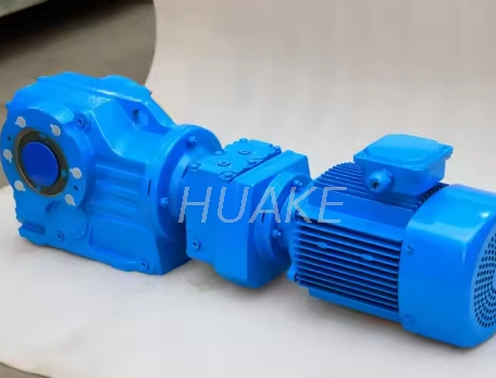
Bevel gear reducers are primarily used when mechanical power needs to change direction between intersecting shafts. In industrial machinery, this normally means a right-angle arrangement where the input and output shafts are positioned approximately 90 degrees apart. Spiral bevel gears use curved teeth that engage progressively, helping provide smooth transmission and good efficiency under continuous operation. Many industrial K-series reducers combine helical stages with a spiral bevel stage, allowing them to achieve useful reduction ratios while changing the direction of the drive. This structure makes them particularly useful in conveyors, packaging equipment, mixers, automation systems, transfer lines, and other machines with restricted installation geometry. HUAKE's KA47 Spiral Bevel Gear Reducer is a right-angle design intended for light to medium industrial machinery. The main advantage of a bevel reducer is that the machine designer can turn the transmission direction without using additional chain drives, belts, or external shaft arrangements. This can simplify the mechanical layout and reduce the number of separate transmission components. Bevel reducers are also often preferred over worm gearboxes when continuous-duty efficiency and lower heat generation are important. Their internal design is more complex than a basic worm reducer, so purchase cost may be higher in some applications. However, lifecycle cost can favor bevel gearing when the machine runs for long hours and electricity use becomes significant. Engineers should therefore compare installation space and initial price together with operating efficiency, load, maintenance, and expected service life.
Bevel and worm gear reducers can both create a compact right-angle drive, but their internal contact mechanisms are different. Spiral bevel gearing primarily transmits power through rolling and sliding contact between shaped gear teeth. Worm gearing involves greater sliding contact between the worm and worm wheel. This difference can affect efficiency, heat generation, lubricant behavior, and long-term energy consumption. A bevel reducer is often attractive for continuous industrial service where efficiency is a major purchasing factor. A worm reducer may still be attractive when high ratio, simple construction, compact size, or budget is more important than maximum transmission efficiency. The motor power also influences the choice because transmission losses become increasingly significant as power and operating hours increase. Thermal conditions should be checked when a gearbox operates in warm environments or inside enclosed machinery. Shaft arrangement alone therefore does not determine which right-angle reducer is best. Engineers also need to compare required ratio, torque, starting load, duty cycle, noise, allowable temperature, and maintenance access. A short-cycle positioning application may justify a different choice from a conveyor that operates continuously through multiple production shifts. The right-angle gearbox should therefore be selected from the complete operating profile rather than simply from its ability to turn the drive by 90 degrees.
Worm gear reducers use a screw-like worm shaft that meshes with a larger worm wheel to reduce speed and change the direction of transmission. Their input and output shafts are usually positioned at approximately 90 degrees, which makes the gearbox convenient for machinery where installation space is limited. A major advantage of worm gearing is that relatively large reduction ratios can be achieved in a compact mechanical package. This makes worm reducers common in conveyors, small mixers, gates, lifting mechanisms, packaging equipment, positioning machines, and general industrial drives. HUAKE's Compact Aluminum NMRV Worm Gearbox is an example of a modular worm reducer intended for universal mechanical transmission. Aluminum housings can reduce gearbox weight and support heat dissipation in suitable light and medium industrial applications. Worm gearboxes can also provide relatively smooth and quiet operation when properly selected and lubricated. However, the sliding contact between the worm and wheel creates different efficiency characteristics from helical or spiral bevel gearing. This sliding action can generate additional heat, particularly at certain ratios and loads. Lubricant selection, thermal capacity, duty cycle, and operating temperature therefore deserve careful attention. A worm reducer can be a very effective solution when its compact design and ratio advantages match the machine, but it should not automatically be selected whenever a right-angle gearbox is required.
A worm reducer makes sense when machine layout and reduction ratio are more important than achieving the highest possible mechanical efficiency. Compact machinery often benefits from the right-angle geometry because the motor can be positioned alongside the driven mechanism rather than extending outward from it. Equipment manufacturers may also prefer worm gearboxes because they are available in many standardized frame sizes and mounting arrangements. Low-speed mechanisms can use higher worm ratios without requiring several large external gear stages. Intermittent operation can reduce the importance of continuous energy losses compared with equipment that runs 24 hours a day. Small conveyors, gates, indexing systems, handling machines, and general-purpose industrial equipment can therefore be suitable applications. Designers should nevertheless calculate output torque instead of assuming that a high reduction ratio automatically produces unlimited usable torque. The gearbox still has structural, bearing, shaft, and thermal limits. Backdriving behavior also needs to be checked because it is unsafe to assume that every worm gearbox is self-locking under every load, ratio, lubrication condition, and vibration level. Efficiency should be evaluated at the actual ratio and operating load rather than from one generic percentage. If the machine will operate continuously at significant power, a bevel or helical design may justify a higher initial cost through lower long-term losses. Worm gear selection should therefore be based on ratio, duty, torque, thermal conditions, safety, and installation space together.
Planetary gear reducers use a central sun gear, several planet gears, a planet carrier, and an outer ring gear to distribute torque through multiple gear contacts. Because several planet gears can share the load simultaneously, planetary reducers can transmit substantial torque within a relatively compact diameter. This torque density makes them popular in automation, servo systems, machine tools, packaging equipment, positioning systems, and other applications where space and performance are both important. The coaxial structure also makes it convenient to connect a servo or other motor directly in line with the driven mechanism. Precision planetary reducers can be manufactured with controlled backlash, making them more suitable for repeated positioning than many standard industrial gearboxes. Low backlash helps reduce lost motion when a servo axis reverses direction. Torsional rigidity is another important factor because a flexible drivetrain can reduce positioning response even when nominal backlash is small. Planetary reducers can also be built in multiple stages when higher ratios are required. Every additional stage changes dimensions, inertia, efficiency, and cost, so the highest ratio is not automatically the best configuration. Servo applications should consider motor inertia and load inertia together because the gearbox affects how the motor responds during acceleration and deceleration. Output bearing capacity is also important where the gearbox directly supports a pulley, pinion, rotary table, or other external load. A planetary reducer is therefore most valuable when compact torque transmission, dynamic response, and positioning performance justify its more specialized construction.
Precision planetary gearboxes should not be specified automatically for every speed-reduction application because their benefits are most valuable in motion-control systems. A normal conveyor that runs continuously in one direction may not benefit from extremely low backlash. In that case, an industrial helical or bevel reducer can provide reliable transmission without the added cost of precision manufacturing. A servo-driven indexing table has different requirements because repeated reversal can expose every degree of lost motion in the gear train. A robot, pick-and-place unit, CNC auxiliary axis, or automated assembly machine may therefore justify a precision planetary reducer. Torsional stiffness should be checked together with backlash because both affect positioning response. Rated output torque is also different from emergency or peak torque, so short acceleration loads should be considered during selection. Input speed can be relatively high in servo applications and must remain within gearbox limits. Lubrication should support the expected operating temperature and speed range. Mounting accuracy also matters because a precision gearbox connected poorly to the machine cannot deliver the expected drivetrain performance. The motor adapter and input coupling need to match the servo shaft dimensions accurately. Planetary gearbox selection should therefore consider precision, stiffness, torque, inertia, speed, duty, and mechanical integration as one system.
Cycloidal gear reducers use an eccentric input mechanism to drive one or more cycloidal discs against a ring of pins or rollers. The resulting motion creates a large speed reduction while distributing load across multiple contact points. This design can provide high reduction ratios, strong shock-load resistance, and substantial output torque in a compact package. Standard cycloidal pinwheel reducers are widely used in industrial machines that require low-speed, high-torque transmission and strong durability. Precision RV-type cycloidal reducers extend the concept for robotics and high-precision automation. These designs often combine planetary and cycloidal stages to achieve compact high-ratio transmission with strong rigidity. HUAKE's Precision RV Cycloidal Gear Reducer for Robot Joints is intended for robot joints and other precision industrial transmission applications. Cycloidal reducers are particularly attractive where repeated acceleration, impact loads, or high output torque could challenge conventional small gearboxes. Their large number of simultaneous contact points helps distribute mechanical load through the transmission. Precision versions can also provide low backlash for controlled motion. However, cycloidal drives have different vibration, bearing, lubrication, and manufacturing characteristics from ordinary helical or worm gearboxes. Selection should therefore use application-specific data rather than assuming that high ratio alone makes a cycloidal reducer appropriate. Robotics is one important use, but cycloidal reducers can also support automation, rotary positioning, handling systems, and other high-load low-speed mechanisms.
Cycloidal and planetary reducers often compete in precision automation because both can provide compact torque transmission. Planetary reducers distribute torque across multiple planet gears and can deliver excellent dynamic performance in servo applications. Cycloidal reducers use a different mechanism with many contact points and can provide strong shock-load capability and high reduction ratios. A precision planetary unit can be attractive where high input speed, moderate ratios, compact inline mounting, and servo integration are priorities. A precision RV cycloidal reducer can be attractive where high rigidity, heavy output torque, impact resistance, and large reduction ratios are required in a compact joint. Robotic applications demonstrate this difference clearly because different robot axes can place different demands on torque, inertia, size, and precision. Backlash must be compared from manufacturer data rather than from gearbox type alone because actual performance depends on design and manufacturing accuracy. The same applies to efficiency and stiffness. Weight can matter significantly on moving robot joints because every kilogram added to one axis increases the load handled by other axes. Output bearing integration is also important where the reducer supports substantial external moment loads. Maintenance and expected life should be considered for machines that perform millions of repeated cycles. The final choice therefore depends on the motion profile rather than a simple statement that cycloidal or planetary technology is always superior.
Cylindrical gear reducers are robust industrial gearboxes built around cylindrical gear sets and are commonly used in heavy mechanical transmission. They are frequently associated with larger machinery where high torque, long operating hours, structural strength, and durable gear construction are more important than achieving the smallest possible gearbox envelope. Parallel shafts are common in these designs, and multiple stages can be used to obtain the required total reduction ratio. Hardened gear teeth can support high load capacity and improve wear resistance when combined with correct lubrication and alignment. Mining machinery, metallurgy, bulk-material handling, large conveyors, industrial processing equipment, and other heavy-duty systems are common application areas. Cylindrical reducers can be physically larger than compact planetary or worm units, but industrial machines often have sufficient installation space to accommodate them. Their larger housing also provides room for substantial shafts, bearings, and gear sets capable of handling demanding mechanical loads. Thermal management is still important because large power transmission generates heat even when mechanical efficiency is good. Oil volume, lubrication method, operating temperature, bearing arrangement, and cooling options may therefore form part of the selection process. External shaft loads should be checked when large couplings, pulleys, or other transmission components connect directly to the gearbox. Foundation stiffness and alignment become increasingly important as gearbox size and torque rise. Cylindrical reducers are therefore best viewed as industrial power-transmission equipment rather than simply larger versions of small gear motors.
The practical difference between reducer types becomes clearer when the same machine requirements are compared across several designs. Helical reducers are strong all-round choices for industrial applications requiring efficient continuous transmission. Bevel reducers provide similar industrial reliability while solving right-angle layout requirements. Worm reducers prioritize compact right-angle installation and convenient high-ratio reduction. Planetary reducers prioritize torque density and precision in compact coaxial systems. Cycloidal reducers prioritize high ratios, load distribution, shock resistance, and precision in selected configurations. Cylindrical reducers focus on robust heavy-duty power transmission for large machinery. Efficiency varies not only between gear types but also according to ratio, number of stages, load, speed, and lubrication conditions. Backlash also varies by individual product design, so a precision planetary reducer cannot be compared fairly with a standard industrial worm gearbox using only generic gearbox categories. Installation space may eliminate some options before efficiency or cost is even considered. Motor orientation can also influence the decision because right-angle reducers can fit where inline gearboxes cannot. Purchase price should therefore be treated as only one part of the comparison. Operating energy, maintenance, downtime, replacement availability, and expected service life can be more significant over years of machine operation.
| Requirement | Likely Reducer Direction |
|---|---|
| Efficient continuous conveyor duty | Helical |
| Efficient 90° industrial transmission | Bevel |
| Compact high-ratio right-angle drive | Worm |
| Compact servo transmission | Planetary |
| High-ratio precision robot joint | Cycloidal / RV |
| Heavy industrial power transmission | Cylindrical |
| Low backlash positioning | Precision planetary or cycloidal |
| Simple economical general reduction | Worm or standard helical, depending layout |
Choosing the correct reducer type begins with the operating data rather than with a preferred gearbox family. First record the motor power and normal input speed because these define the mechanical power entering the transmission. Then determine the required output speed so the approximate reduction ratio can be calculated. Continuous output torque should be established from the real machine load rather than estimated only from motor size. Starting torque and shock loads should be considered separately because they may be several times higher than normal operating torque. Duty cycle matters because a gearbox running continuously faces a different thermal condition from one operating a few minutes per hour. Shaft arrangement should then be identified because some machines require inline transmission while others need parallel or right-angle output. Available installation space can further narrow the possible reducer types. Precision requirements should be documented if the machine reverses frequently or performs controlled positioning. Efficiency becomes more important as motor power and annual operating hours increase. Ambient temperature, dust, moisture, corrosive chemicals, washdown, and outdoor exposure can influence housing, seals, lubricant, and motor protection requirements. The final selection should compare several appropriate reducer structures against the same operating data instead of choosing a product first and trying to adapt the machine around it.
| Requirement | Questions to Ask |
|---|---|
| Input Power | What motor kW or HP will drive the reducer? |
| Input Speed | What are normal and maximum rpm? |
| Output Speed | What machine speed is required? |
| Gear Ratio | What ratio produces that speed? |
| Continuous Torque | What load operates most of the time? |
| Peak Torque | What happens during start, stop, or jam? |
| Operating Hours | Intermittent or continuous duty? |
| Shaft Layout | Inline, parallel, or right-angle? |
| Precision | Is low backlash necessary? |
| Space | What installation envelope is available? |
| Environment | Dust, moisture, heat, corrosion, outdoor use? |
| Maintenance | How easily can lubricant and seals be serviced? |
There is no single best gear reducer because a gearbox should be matched to the machine's mechanical and operating requirements. A manufacturer choosing a drive for a continuously running bulk conveyor may prioritize efficiency, torque capacity, and service life, which can favor a helical design. A packaging machine with limited space and a 90-degree shaft arrangement may favor a compact bevel reducer. A small mechanism requiring a large ratio in a short right-angle housing may make a worm reducer practical. A servo indexing system may favor a planetary gearbox because precision and dynamic response matter more than simple cost. An industrial robot joint may favor a precision cycloidal design because the axis requires compact high torque, strong rigidity, and repeated positioning. A heavy mining drive may require a much larger cylindrical or heavy industrial gearbox with strong shafts and bearings. The gearbox also needs to match the motor, coupling, output shaft, frame, and driven machine, so reducer selection cannot be separated from overall mechanical design. Engineers should compare usable torque rather than theoretical torque multiplication alone. Gearbox thermal capacity should also be checked when operation is continuous or ambient temperature is high. Service factor should reflect the severity of the application instead of using the same value across every machine. The best gearbox is therefore the one that meets torque, speed, precision, efficiency, packaging, durability, and maintenance requirements without unnecessary oversizing.
HUAKE provides several gear reducer technologies that allow industrial buyers to select a transmission structure according to the application rather than adapting every machine to one gearbox family. Its current product range covers helical, bevel, planetary, worm, cycloidal, and cylindrical gear reducers, as well as gear motors and worm gear screw jacks. Helical reducer options can support conveyors, industrial production equipment, processing machinery, and other continuous-duty transmission systems. Bevel gear reducers provide right-angle solutions for machinery where efficient directional change and compact installation are required. Worm reducers provide another right-angle option for applications where ratio range, compact construction, and general mechanical transmission are priorities. Planetary reducers address compact high-torque and precision transmission requirements. Cycloidal reducers extend the range toward high-ratio, impact-resistant, and robotic motion applications. Cylindrical and heavy industrial gearboxes support larger mechanical drives where structural capacity becomes a primary concern. Buyers should provide HUAKE with motor power, input speed, output speed, required torque, peak load, operating hours, mounting arrangement, shaft requirements, and environmental conditions before requesting final selection. Precision applications should also specify acceptable backlash and motion characteristics. Existing equipment replacement projects should include current gearbox dimensions and shaft details so mechanical interchangeability can be evaluated. A broad product portfolio is most useful when it allows several transmission concepts to be compared against the same machine requirement rather than simply increasing the number of catalog models.
The main types of gear reducers include helical, bevel, worm, planetary, cycloidal, and cylindrical designs, and each type solves a different combination of transmission requirements. Helical reducers provide smooth and efficient operation for many general industrial drives. Bevel reducers are especially useful when power must be transmitted through a right-angle layout without sacrificing the efficiency expected from geared industrial machinery. Worm reducers provide compact right-angle transmission and can achieve large ratios in a relatively simple package. Planetary reducers offer high torque density and are widely used where compact size and precision motion matter. Cycloidal reducers provide high reduction ratios, strong impact resistance, and precision capability for robotics and other demanding automation applications. Cylindrical reducers support heavy industrial power transmission where load capacity and structural durability dominate the design. The gearbox type should never be selected from ratio alone because torque, duty cycle, efficiency, mounting, backlash, thermal conditions, and environment all influence performance. Initial price should also be compared with energy use, maintenance, service life, and downtime. A reducer that is inexpensive to purchase can become costly if it operates inefficiently or is poorly matched to the load. HUAKE provides several reducer structures that can be evaluated for different mechanical systems and industrial applications. The most effective selection process starts with complete machine data and then compares the reducer technologies that can satisfy those requirements.
The main types include helical, bevel, worm, planetary, cycloidal, and cylindrical gear reducers. Helical reducers use angled gear teeth for smooth industrial transmission. Bevel reducers change the direction of power between intersecting shafts. Worm reducers combine a worm and worm wheel for compact right-angle reduction. Planetary reducers distribute torque across several planet gears. Cycloidal reducers use eccentric cycloidal motion and multiple contact points. Cylindrical reducers are commonly used for robust industrial power transmission. Each type provides a different combination of efficiency, ratio, size, torque, and precision. Shaft arrangement also differs between gearbox designs. Some applications can use several reducer types successfully. Final selection should therefore be based on the complete machine requirements rather than the gearbox name alone.
Several reducer types can provide high torque, so the answer depends on the operating conditions. Planetary reducers provide high torque density within compact dimensions. Cycloidal reducers can also transmit substantial torque and handle shock loads effectively. Large helical and cylindrical gearboxes are widely used for heavy industrial torque transmission. A gearbox rated for high torque may still be unsuitable if its shaft arrangement does not fit the machine. Output bearing capacity must also be considered. Peak torque is different from continuous rated torque. Starting and impact loads should be included during selection. Gear ratio affects torque multiplication but does not remove gearbox structural limits. Thermal capacity can become important in continuous operation. The best high-torque reducer is therefore the design that meets torque, speed, mounting, duty, and service-factor requirements together.
Helical and bevel gear reducers can provide high transmission efficiency in many industrial applications. Planetary gearboxes can also offer efficient power transmission when properly sized. Worm reducer efficiency can vary more significantly because the worm and wheel have greater sliding contact. The actual efficiency depends on ratio, number of stages, input speed, lubricant, temperature, and load. A lightly loaded gearbox may not operate at the same efficiency as one operating near its intended design point. Multiple reduction stages also introduce additional losses. Manufacturing accuracy influences gear contact and friction. Correct lubrication is essential for efficient operation. Long operating hours make small efficiency differences more important economically. A continuously running industrial machine should therefore compare manufacturer efficiency data at the intended operating point. No gearbox type should be assigned one universal efficiency percentage for every model and ratio.
Helical gear reducers are widely used for conveyor systems because they provide smooth transmission, good efficiency, and strong continuous-duty performance. Parallel-shaft helical reducers can be particularly useful where installation length is limited. Bevel reducers can be selected when the conveyor layout requires a right-angle motor arrangement. Worm gearboxes may suit smaller or intermittent conveyors where compact construction and cost are priorities. Heavy bulk conveyors can require much larger industrial gearboxes. The required torque depends on belt loading, starting conditions, incline, friction, and conveyor length. A fully loaded startup can require much more torque than normal running. Operating hours also affect gearbox selection. Output shaft and mounting arrangements should fit the pulley or conveyor frame. Environmental dust and moisture should be considered. The correct conveyor reducer should therefore be selected from the actual conveyor calculations rather than from conveyor width alone.
Planetary reducers use a sun gear, multiple planet gears, a carrier, and a ring gear. Cycloidal reducers use eccentric cycloidal discs or related mechanisms engaging with multiple pins or rollers. Planetary designs can provide compact torque transmission and good servo response. Precision planetary reducers are widely used in automation and positioning systems. Cycloidal reducers can provide high ratios and strong resistance to shock loading. Precision RV cycloidal units are widely associated with robotic joint applications. Both types can be manufactured with low backlash. Their rigidity, efficiency, weight, and inertia vary by design. Input and output bearing arrangements can also differ. The correct choice depends on motor speed, ratio, load, positioning accuracy, shock load, dimensions, and duty cycle. It is therefore better to compare specific gearbox specifications than to assume one technology is always more precise.
Both can provide a right-angle transmission arrangement, but they use different gear mechanisms. A bevel reducer uses bevel or spiral bevel gears between intersecting shafts. Many industrial designs also combine helical and bevel stages. A worm reducer uses a screw-like worm engaging a worm wheel. The greater sliding contact in worm gearing can create different efficiency and thermal characteristics. Bevel gearing is often attractive for continuous industrial applications where efficiency matters. Worm reducers can offer compact construction and high reduction ratios. Initial purchase cost may also differ. Machine size can influence which configuration fits more easily. Duty cycle should be considered because continuous losses matter more in long-running machines. Backdriving requirements should also be evaluated carefully. The best right-angle gearbox depends on ratio, torque, efficiency, heat, space, and lifecycle cost.
Start with motor power and input speed. Determine the required output speed and calculate the approximate reduction ratio. Calculate continuous load torque and identify any peak or shock loads. Define how many hours per day the gearbox will operate. Identify whether the shafts need to be inline, parallel, or right-angle. Determine whether low backlash is required for positioning. Measure the available installation space. Check the ambient environment for dust, moisture, chemicals, or high temperature. Define the required mounting method and output shaft connection. Consider transmission efficiency when the machine operates for long periods. Then compare several reducer technologies that can meet these requirements. Final model selection should use manufacturer torque, thermal, bearing, speed, and service-factor data rather than ratio alone.


