
- All
- Product Name
- Product Keyword
- Product Model
- Product Summary
- Product Description
- Multi Field Search


Views: 0 Author: Site Editor Publish Time: 2026-10-15 Origin: Site


Does gear noise disrupt your factory floor? Poor component selection often causes costly downtime and relentless maintenance headaches. Helical gears solve these mechanical failures. They utilize angled teeth that ensure remarkably smooth power transmission. We will explore the underlying mechanics of these components, examine their diverse configurations, compare them to standard alternatives, and outline how to select the right equipment for specific industrial applications.
Engineers must examine the underlying mechanical geometry to understand why these drive systems outperform standard options. Standard gears feature teeth cut perfectly parallel to the rotational axis. In contrast, this design features teeth cut at a specific diagonal angle to the face of the cylinder. This critical geometric feature is known as the helix angle.
The primary mechanical advantage of this angle is the gradual engagement of the teeth. When a maintenance engineer observes these components meshing, they will notice that contact begins at one extreme end of the tooth face. As the mechanism rotates, this contact point gradually sweeps across the entire surface. This fundamentally differs from straight-cut designs. In straight-cut setups, the entire face of the tooth engages simultaneously, causing a sudden and harsh impact.
Consequently, this gradual meshing process results in a higher contact ratio. Multiple teeth are actively engaged and sharing the mechanical load at any given moment. This distributed stress translates to significantly less vibration and drastically reduced metal fatigue. It also provides the ability to transmit higher torque loads at elevated rotational speeds. Precision machinery cannot tolerate micro-fluctuations in speed. For these applications, this continuous contact ensures an absolutely constant velocity ratio.
Recent industrial analyses reveal a massive shift in power transmission technology. Modern manufacturing facilities face strict energy regulations and demand higher throughput. Legacy drive systems simply cannot keep up with these grueling parameters. Engineers are rapidly adopting precision-engineered enclosed reducers to solve this. These advanced systems minimize power loss, drastically reduce acoustic pollution, and guarantee stable 24/7 operation.
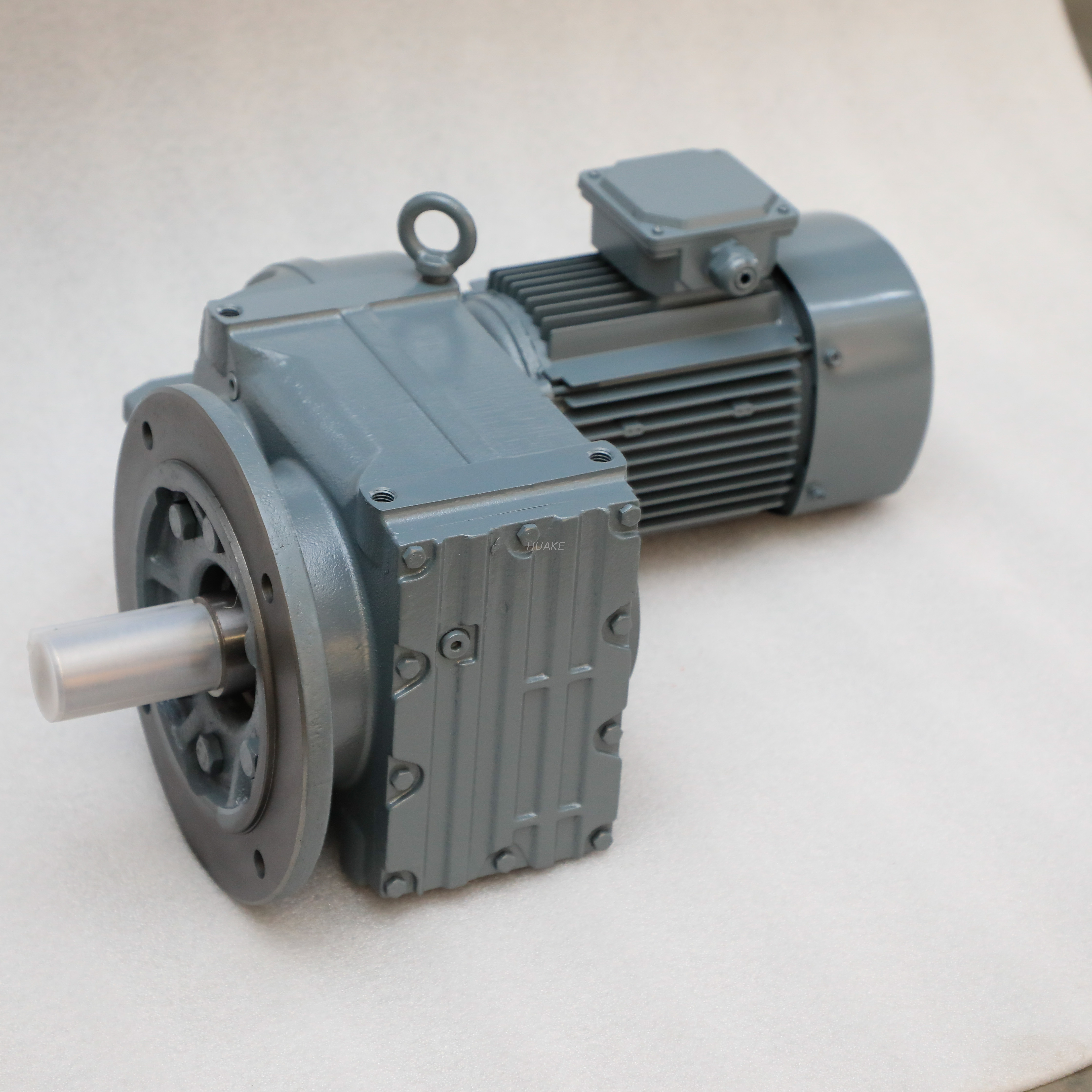
Selecting the correct configuration is a make-or-break decision in mechanical design. The physical orientation of the machine shafts and the required load capacity dictate which variation is most appropriate for your specific application.
The Parallel Shaft Helical Gear is explicitly engineered to operate on parallel axes. The input motor shaft and the output drive shaft run perfectly parallel to one another in this setup. To mesh correctly, the helix angles of the mating components must be equal but opposite in hand. One must have a right-hand twist and the other a left-hand twist.
These units are renowned for their exceptional mechanical efficiency. They frequently exceed 95 percent efficiency in well-lubricated enclosed systems. They form the rugged backbone of heavy-duty industrial processing. You will find them deployed heavily in mining crushers, large-scale aggregate conveyors, and bulk material handling machinery where continuous power delivery is non-negotiable.
Operating within a coaxial setup, the Inline Helical Gear presents an entirely different spatial solution. The input shaft from the prime mover and the output shaft of the gearbox are aligned in a straight, continuous line. Internally, the drive train utilizes multiple reduction stages to slow rotational speed and multiply torque while maintaining this strict linear footprint.
The standout advantage here is space-saving geometry. Automation engineers heavily favor this design when building compact machinery. When the lateral width of the machine is severely restricted, keeping the power transmission linear allows facilities to design slimmer equipment without sacrificing an ounce of torque output.
Crossed axis variations are utilized when power must be transmitted between non-intersecting and non-parallel shafts. Typically, these shafts are oriented at a strict 90-degree angle to one another. Unlike parallel setups, crossed axis designs can actually feature the same hand of helix. This depends entirely on the specific shaft angle.
Mechanically speaking, these components experience point contact rather than line contact during the meshing cycle. The entire contact area is concentrated on a microscopic point. Therefore, they are subject to much higher localized stress and sliding friction. As a result, engineers strictly reserve them for lighter load applications, such as instrumentation panels, timing mechanisms, and light-duty rotary control.
Single angled teeth inherently generate an axial thrust force. This force actively pushes the gear laterally along its shaft during operation. Double helical designs were invented specifically to counteract this physical phenomenon. They feature two distinct sets of teeth cut at opposite angles on the exact same gear blank. A narrow central groove usually separates these two sides.
Herringbone gears act as a specific subset of this design. The two sets of teeth meet perfectly in the center without any groove, forming a continuous V shape. The brilliance of both designs is that the opposite angles generate equal and opposite axial thrust forces. These forces effectively cancel each other out entirely. This self-aligning feature allows them to handle massive load capacities without requiring heavy thrust bearings. They are ideal for marine propulsion systems and heavy steel rolling mills.
When specifying components for a new production line, engineers frequently evaluate angled designs against standard spur gears. Both serve the fundamental purpose of transmitting motion. However, their structural differences yield wildly distinct operational profiles.
The structural divergence lies entirely in the teeth. Spur gears feature straight teeth cut parallel to the axis of rotation. In contrast, the angled teeth of a helical setup create a spiral geometry along the cylinder. This single difference dictates their behavior on the factory floor.
| Gear Type | Tooth Design | Noise Level | Load Capacity | Axial Thrust |
|---|---|---|---|---|
| Standard Spur | Straight and parallel | High | Moderate | None |
| Single Helical | Angled single twist | Very Low | High | High |
| Double Helical | V-shaped opposing angles | Extremely Low | Very High | Canceled |
Imagine a high-speed packaging line. Spur gears are infamous for their operational noise in such environments. They emit a high-pitched whine at high RPMs. This acoustic pollution occurs because the straight teeth engage simultaneously across their entire width. This creates a rapid-fire series of impact forces. Angled teeth mitigate this entirely through their sliding, gradual contact. They absorb the impact and allow the setup to remain exceptionally quiet and physically stable.
Furthermore, because multiple teeth are engaged simultaneously, angled setups carry significantly heavier loads. Spur gears do possess a slight advantage in raw mechanical efficiency. Because they lack an angle, they generate zero axial thrust and experience less sliding friction. This results in marginally higher energy transfer. Ultimately, spur gears are suitable for low-speed and low-cost applications. Angled designs remain the definitive choice for high-speed and high-torque industrial environments.
In heavy industrial settings, raw motor speed is rarely suitable for direct application. Electric motors spin at high velocities but lack the brute force needed to move heavy physical loads. This is where a Helical Gear Reducer becomes an indispensable piece of infrastructure. Placed directly between the motor and the driven machinery, this enclosed gearbox systematically slows down the input speed while proportionally multiplying the torque output.
The decision to utilize this specific gearing within reducers is driven purely by the demand for durability. Industrial sectors such as mining, chemical mixing, and automotive assembly require continuous power delivery. The progressive tooth engagement minimizes internal shock loads. This drastically extends the lifespan of the equipment. Furthermore, these units integrate seamlessly with standard AC or DC motors. They create unified gearmotors that simplify installation and ensure thermal stability during continuous duty.
For procurement managers tasked with upgrading power transmission systems, selecting the right gearbox series is just as critical as understanding the internal mechanics. Two of the most prominent industrial configurations tackle spatial and operational challenges in vastly different ways.
The R Series Reducer is built entirely around an inline layout. The motor input and the gearbox output share the exact same rotational axis. This results in a robust and cylindrical housing.
Characterized by high energy efficiency and a highly compact axial footprint, this series stacks its internal reduction stages linearly. This architectural choice offers a massive range of gear ratios within a relatively small diameter. It is highly rigid and designed to withstand substantial radial loads. Consequently, it is the standard choice for inline conveyor systems, fluid agitators, and industrial water pumps where the machinery layout naturally accommodates a long, straight drive train.
Conversely, the F Series Reducer utilizes a parallel shaft layout. The internal shafts run side-by-side. This results in a deliberate offset between the input motor and the final output shaft.
The defining feature of this series is its extremely slim and flat profile. When a maintenance team is trying to squeeze a powerful drive unit into a tight lateral space, a bulky inline unit simply will not fit. Think of the narrow gap between a factory wall and a bucket elevator. Despite its incredibly narrow footprint, the parallel design provides phenomenal structural rigidity and transmits immense torque. It is engineered specifically for heavy-duty conveying systems, overhead cranes, and hoists where space is constrained but power is mandatory.
An objective evaluation of these drive mechanisms requires a clear understanding of both their mechanical benefits and their inherent engineering challenges. They are highly efficient, but they are not a universal cure-all for every engineering problem.
The most significant benefit is their high load-carrying capacity. The multiple-tooth contact ratio allows these systems to transmit much heavier loads without structural failure compared to straight-cut equivalents. In addition, the sweeping engagement of the teeth eliminates percussive impact forces. This results in exceptionally smooth and quiet operation. Finally, their versatility is unmatched. Depending on the specific cut, they can be adapted to parallel, inline, or right-angle shaft orientations to fit complex machinery layouts.
The primary drawback is a direct consequence of their greatest strength: axial thrust. As the angled teeth push against one another to transmit torque, they create a lateral side-load. This force attempts to slide the gear off its shaft. To solve this, mechanical engineers must integrate specialized thrust bearings into the housing. Tapered roller bearings are commonly used to safely absorb this force. Additionally, the complex geometry makes them more expensive to manufacture. However, savvy procurement teams recognize that the extended operational lifespan and reduced maintenance downtime consistently offset the higher initial capital expenditure.
Selecting the optimal configuration requires a systematic and evidence-based evaluation of the mechanical environment. Engineers and buyers should follow these strict criteria when specifying new systems.
First, rigorously assess the spatial constraints. The physical footprint of your machinery dictates the gearbox type. If the application demands a straight and continuous drive line, an inline configuration is appropriate. If lateral space is highly restricted and the motor must be tucked flat alongside the machinery, a parallel shaft configuration is absolutely required.
Next, calculate precise load and torque requirements. It is never enough to simply match horsepower. Evaluate the nominal torque, peak start-up torque, and the required industry service factor. You must ensure the selected unit matches the operational stress of your specific application.
Finally, consider operating speeds, noise limits, and bearing integration. If your facility enforces strict occupational noise limits, precision-ground angled teeth are mandatory. Crucially, never specify a single-angle system without verifying that the manufacturer has integrated robust thrust bearings. These bearings must be rated to handle the continuous lateral load over the entire duty cycle of the machine.
Understanding the nuanced differences between various gear configurations is paramount for optimizing industrial performance. From space-saving inline setups to the rugged and flat profile of parallel shaft designs, these mechanisms provide tailored solutions for complex engineering challenges.
While they do introduce axial thrust that requires careful bearing selection, their ability to deliver smooth, quiet, and uninterrupted high-torque power makes them the undisputed choice for modern heavy industry. By carefully evaluating spatial constraints and load requirements, facilities can select the perfect reducer to drastically improve machine reliability.
If you are looking to upgrade your power transmission systems, choosing a reliable manufacturer is crucial. For precision-engineered solutions tailored to heavy-duty applications, explore the comprehensive range of industrial gearboxes at Huake Gearbox to find the exact R Series or F Series reducer that fits your operational needs.
They are named after the mathematical helix angle at which their teeth are cut. Instead of being perfectly parallel to the axis of rotation, the teeth cut across the gear face at a diagonal angle. This resembles a spiral or helix shape. This unique and sweeping geometry is exactly what allows for their signature smooth and continuous mechanical operation.
Yes, they are fully capable of running in reverse without damaging the teeth. However, there is a critical engineering caveat. Reversing the rotational direction will also instantly reverse the direction of the axial thrust force. The gearbox housing and internal bearings must be specifically engineered to handle bi-directional thrust loads safely.
The primary difference lies entirely in the shaft orientation and resulting physical shape. The R Series utilizes an inline coaxial design. This means the input and output shafts are aligned in a straight line, creating a long and cylindrical shape. The F Series uses a parallel shaft design. It places the shafts side-by-side, which creates a much flatter and space-saving profile ideal for tight clearances.
Standard spur gears actually possess a slightly higher raw mechanical efficiency, often near 99 percent. This is because their straight teeth do not generate sliding friction or axial thrust. However, angled designs are far superior in real-world high-speed and high-load applications. In these harsh environments, the extreme vibration and impact noise would cause spur gears to fail or wear out rapidly. This makes the angled alternative the far more efficient and reliable long-term choice.
In well-lubricated enclosed systems, they routinely achieve mechanical efficiencies between 95 and 98 percent. The exact figure depends heavily on the helix angle, the quality of the synthetic lubricant used, and the number of internal reduction stages inside the gearbox.
Worm gears are excellent for achieving massive reduction ratios in very tight spaces. However, they suffer from significant sliding friction, which causes high heat generation and much lower mechanical efficiency. Angled tooth designs provide much higher energy transfer rates, run significantly cooler, and have a much longer operational lifespan under continuous heavy loads.


