
- All
- Product Name
- Product Keyword
- Product Model
- Product Summary
- Product Description
- Multi Field Search


Views: 0 Author: Site Editor Publish Time: 2026-10-13 Origin: Site


Standard electric motors typically spin at blistering speeds. These velocities often exceed 1800 or 3600 revolutions per minute. While this raw speed looks impressive on a spec sheet, it is fundamentally useless for heavy machinery. Heavy-duty equipment demands immense pushing, pulling, or lifting power. Connect a high-speed motor directly to a loaded mining conveyor, and the system will instantly stall, overheat, or shear its own shaft. Engineers control this overwhelming speed and convert it into usable force by achieving high torque at lower speeds. This mechanical feat is perfectly executed by a gear reduction motor.
Recent industry trend analyses reveal a massive global shift toward smart manufacturing and energy conservation. Facilities across the globe are rapidly moving away from legacy, energy-hungry drive systems. Instead, they favor compact, high-efficiency powertrains that meet strict IE3 and IE4 energy standards. Modern industrial operators now demand gear systems that drastically reduce carbon footprints while integrating seamlessly with IoT diagnostics. Vibration sensors and thermal monitors are becoming standard add-ons, allowing plant managers to transition from reactive repairs to highly accurate predictive maintenance. In this comprehensive guide, we will explore the internal mechanics of these critical components, compare popular architectural configurations, and provide actionable criteria for selecting the ideal unit for your specific operational environment.
At its core, this device is an integrated electromechanical assembly comprising two primary sections. The first is an electric motor powered by either alternating current or direct current. This motor acts as the prime mover, generating high-speed, low-torque rotational energy. Immediately adjacent to it, the attached mechanical gearbox receives this kinetic energy. The internal gear train then mathematically translates that rapid rotation into a low-speed, high-torque output.
In the realms of industrial engineering and procurement, professionals frequently rely on interchangeable terminology. Whether you see a product labeled as a gear motor, a geared motor, or a Speed Reducer Motor, they all refer to this exact same integrated assembly. Regardless of the specific nomenclature on the engineering spec sheet, the fundamental purpose remains identical. These units adapt the raw, uncontrollable speed of a motor to the practical, heavy-lifting requirements of driven machinery.
Historically, facility engineers purchased electric motors and standalone gearboxes as entirely separate entities. They awkwardly connected them on the factory floor via external couplings, belts, or drive chains. However, modern factory integration offers profound mechanical advantages that render those older methods obsolete.
First and foremost, factory integration ensures microscopic alignment between the motor shaft and the gearbox input. This tight tolerance eliminates the persistent risk of coupling misalignment. Misalignment is a notorious culprit behind premature bearing failure and severe shaft vibration. Consequently, a combined unit features a much tighter, more compact design. This saves valuable spatial footprint in cramped machinery layouts. Furthermore, integrated systems drastically reduce routine maintenance burdens. With fewer external moving parts, no drive belts to constantly re-tension, and no exposed couplings requiring manual lubrication, operational uptime increases significantly.
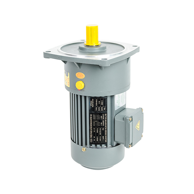
The fundamental physics driving these systems relies heavily on the principle of mechanical advantage. The internal gear train operates on an inverse relationship between speed and torque. As the rotational speed systematically decreases while traveling through the meshing gears, the rotational force increases proportionally. You only lose a small percentage of energy to internal friction.
Consider a practical analogy of riding a multi-speed mountain bike. When you shift into a lower gear to climb a steep, rocky hill, you are forced to pedal much faster to turn the rear wheel very slowly. However, this low gear provides the immense pushing force required to propel your body weight up the severe incline. Industrial powertrains apply this exact mechanical logic to move tons of raw material across a factory floor.
To properly size a system, you must understand the gear ratio. This is the mathematical representation of the speed reduction process. It is calculated by dividing the number of teeth on the driven output gear by the number of teeth on the driving input gear.
For instance, if a system features a gear ratio of 50 to 1, the motor internal rotor must complete exactly 50 full rotations to turn the final output shaft just one time. If the base electric motor operates at 1500 revolutions per minute, passing that power through a 50 to 1 ratio yields a final, usable output speed of 30 revolutions per minute. Simultaneously, the output torque is multiplied by a factor of 50, delivering the concentrated power necessary for heavy industrial tasks.
The transfer of mechanical power inside the housing follows a precise pathway. Initially, the electric motor stator and rotor generate high-speed rotational energy. This kinetic energy travels directly along the motor shaft to the primary input pinion, which is typically the smallest gear in the entire box. From there, the pinion drives a significantly larger intermediate gear. Because this intermediate gear has a larger circumference, it turns slower but pushes with considerably greater force. This engaging process may repeat across two, three, or even four gear stages depending on the depth of the required reduction ratio.
Selecting the correct internal gear topology is a critical engineering decision. It directly impacts performance, acoustic output, and long-term maintenance budgets. Below are the predominant configurations utilized across global industrial sectors.
| Gear Type | Average Efficiency | Noise Level | Best Application Scenario |
|---|---|---|---|
| Helical | 95% to 98% | Very Low | Continuous-duty conveyors, heavy manufacturing |
| Worm | 50% to 80% | Low | Vertical lifting, hoists, tight spatial constraints |
| Planetary | 90% to 95% | Medium | Robotics, servo mechanisms, high torque density needs |
This configuration features cylindrical gears equipped with teeth cut at a specific, calculated angle relative to the face of the gear. This angled geometry allows the gear teeth to engage and disengage gradually, rather than slamming together all at once like traditional spur gears.
Operators primarily favor the Helical Gear Motor because the gradual tooth engagement results in incredibly smooth, vibration-free, and quiet operation. They perform exceptionally well even when running at maximum speeds under heavy loads. Furthermore, helical gears boast exceptional energy transfer efficiency, routinely exceeding 95 percent per stage. They stand as the undisputed industry standard for continuous-duty manufacturing applications where energy conservation and relentless durability are non-negotiable.
Worm systems utilize a threaded, screw-like shaft that actively meshes with a perpendicular toothed wheel. This unique internal geometry inherently forces a right-angle output, making it highly advantageous for installations squeezed into tight corners or narrow conveyor frames.
A defining characteristic of worm gears is their mechanical self-locking capability. In setups with high reduction ratios, the physical friction prevents the output shaft from driving the input shaft backward. This makes them an exceptionally safe choice for vertical lifting applications where preventing a load from free-falling is critical. Conversely, because they operate via sliding friction rather than rolling friction, they generate substantial heat. They are noticeably less efficient than their helical counterparts, often wasting a significant portion of electrical energy.
Planetary architectures consist of a central sun gear surrounded by multiple rotating planet gears, all securely enclosed within an internally toothed outer ring gear. Because the mechanical load is distributed evenly across multiple gear meshes simultaneously, the system can handle massive forces without failing.
This highly engineered design results in an extremely compact physical footprint coupled with an exceptionally high torque density. Planetary systems offer pinpoint precision and virtually zero mechanical play. This makes them the absolute preferred choice for robotics, automated servo mechanisms, and heavy mobile equipment where spatial real estate is at a premium.
Engineers face a harsh reality on the plant floor. No mechanical gearbox is perfectly efficient. Kinetic energy inevitably bleeds off in the form of ambient heat and acoustic noise. These losses stem from the friction between meshing gear teeth, the natural resistance of heavy-duty bearings, and the hydraulic drag caused by gears churning through thick lubricating oil.
The specific gear arrangement you choose heavily dictates the severity of this efficiency loss. A helical setup transfers power through a smooth rolling action, effectively minimizing friction and retaining maximum motor power. In stark contrast, worm gears rely heavily on a sliding action. This sliding friction generates immense heat. Consequently, a significantly larger portion of the electrical energy drawn by the motor is entirely wasted, particularly when operating at higher reduction ratios.
The underlying electrical power source also plays a pivotal role in overall operational efficiency.
Alternating current motors are heavily favored in massive industrial plants. They are highly efficient when tasked with continuous, constant-speed operations. When paired with a premium helical gearbox, an alternating current system provides relentless, year-round power with minimal energy waste. On the other hand, direct current motors offer superior efficiency across a highly variable speed range while delivering massive starting torque. When integrated into a drive system, direct current setups are unparalleled for applications demanding frequent starts, sudden stops, and rapid speed adjustments.
Procuring the correct powertrain requires a highly methodical approach rooted in objective mechanical data rather than rough estimations. Installing an undersized unit guarantees premature failure due to thermal overload or sheared gear teeth. Conversely, an oversized unit needlessly inflates capital expenditures and wastes electricity. To make a technically sound decision, engineering teams must evaluate several critical parameters against real-world product capabilities.
The fundamental job of any geared assembly is converting rapid input into forceful output. Therefore, calculating your exact application requirements is step one. Begin by determining the precise output speed your driven equipment needs to function optimally.
Once the target speed is locked in, you must calculate the required operating torque. This is the actual twisting force needed to move the physical load, generally measured in Newton-meters. Crucially, engineers must differentiate between standard running torque and peak starting torque. A fully loaded, inclined aggregate conveyor requires a massive surge of starting torque just to overcome static friction. When browsing premium catalogs, you will find modern Geared Motor units offering output torque ranging from 130 Newton-meters up to a staggering 50,000 Newton-meters. You must ensure the chosen unit can handle violent initial spikes without exceeding its mechanical shear limits.
The physical environment surrounding the installation site heavily dictates the required housing materials, internal sealing technologies, and cooling mechanisms. A standard motor placed in a highly corrosive or dust-choked environment will suffer accelerated, catastrophic degradation.
Specifically, extreme ambient heat severely restricts a motor ability to shed thermal energy. This often necessitates forced-air cooling fans or high-end synthetic lubricants that resist thermal breakdown. Furthermore, if the application involves heavy dust, chemical sprays, or high-pressure water washdowns, selecting the proper ingress protection rating is non-negotiable. Modern industrial units frequently feature IP66 or IP69K rated stainless steel housings, which are mandatory for food processing washdown environments.
The service factor is a critical safety multiplier applied to a motor nominal power rating. It ensures the unit can survive actual operating conditions without fatigue failure. It accounts for load volatility, daily operating hours, and the frequency of aggressive starts and stops.
A motor driving a smooth, uniform load for a standard eight-hour shift might only require a service factor of 1.0. However, a heavy-duty rock crusher operating twenty-four hours a day, enduring violent shock loads and sudden jams, will absolutely require a service factor of 2.0 or higher. Understanding your exact duty cycle prevents you from overpaying for continuous-duty ratings when a lighter-duty motor would suffice.
Even the most robustly engineered, premium-tier systems require proactive baseline maintenance to achieve their maximum designed lifespan. Implementing a strict, condition-based maintenance schedule minimizes unplanned factory downtime and protects your expensive capital investments.
High-quality lubrication is the literal lifeblood of any gear reduction system. The intense mechanical friction generated between meshing gear teeth creates localized heat spikes. The lubricant acts to minimize metal-to-metal wear while simultaneously transferring heat away from the contact zones to the outer casing.
Always utilize the specific oil viscosity and chemical type mandated by the manufacturer. Introducing the wrong oil chemistry can cause severe foaming, internal seal degradation, or failure to maintain an adequate protective film between the gears. For standard mineral oils operating under normal conditions, complete fluid changes are typically required every 10,000 operating hours. Upgrading to premium synthetic oils can often push this interval to 20,000 hours. During these changes, maintenance technicians must inspect the magnetic drain plugs. An accumulation of metal shavings serves as a critical early warning sign of impending gear failure.
When a mechanical system begins to degrade, it almost always exhibits measurable, physical symptoms long before a total catastrophic breakdown occurs. Training floor operators to recognize these early warning signs is vital.
If a unit exhibits excessive overheating, it is likely suffering from physical overloading, depleted oil levels, or degraded oil viscosity. Unusual grinding noises or high-frequency vibrations typically point toward failing internal bearings, gear tooth pitting, or severe misalignment with the driven load. By deploying modern condition-monitoring tools, maintenance teams can successfully transition from reactive, panic-driven repairs to highly controlled scheduled maintenance.
When procuring critical power transmission components, the engineering pedigree and reliability of the manufacturer are just as important as the raw mechanical specifications on the brochure. Harsh industrial environments simply do not tolerate poorly machined gears, cheap bearings, or substandard housing materials.
Premium manufacturing relies entirely on strict quality control and advanced metallurgical protocols. Top-tier gear systems utilize state-of-the-art CNC gear grinding to achieve mathematically perfect tooth profiles. This ensures maximum surface contact area while virtually eliminating mechanical backlash. This meticulous, uncompromising attention to manufacturing tolerances results in an Industrial Gear Motor that operates quietly, efficiently, and reliably under the most punishing loads imaginable.
Furthermore, standard off-the-shelf catalog solutions rarely fit complex, real-world engineering challenges perfectly. Partnering with a manufacturer that possesses deep application knowledge and offers bespoke custom configurations ensures that the drive system integrates flawlessly into your existing infrastructure. Rigorous end-of-line factory testing, including dynamic load testing and acoustic signature measurements, guarantees that every single unit performs exactly to its published specifications before it ever reaches your loading dock.
A gear reduction powertrain is the ultimate mechanical bridge between raw, high-speed electrical energy and the slow, overwhelming torque required by heavy machinery. It is an indispensable solution for demanding industrial environments where precision, power, and reliability must coexist without compromise.
By taking the time to understand internal mechanics, carefully calculating your exact torque requirements, and accounting for harsh environmental variables, you ensure that your equipment runs efficiently for years. Choosing the right configuration not only prevents catastrophic mechanical failures but also significantly reduces long-term energy consumption and maintenance overhead.
Do not leave your facility operational uptime to chance. Upgrading your power transmission infrastructure requires components empirically proven to withstand daily industrial abuse. We invite you to explore premium, highly durable solutions tailored for maximum mechanical efficiency. Visit Huake Gearbox today to consult with our dedicated engineering team for custom powertrain sizing, expert application advice, and exact project quotes.
A standard electric motor typically spins at extremely high speeds but generates relatively low torque, making it fundamentally incapable of driving heavy, slow-moving machinery directly. A gear motor solves this by integrating a standard motor with a mechanical gearbox inside a single housing. This built-in gear train systematically slows down the rotational speed while proportionally multiplying the torque, allowing the unit to push, pull, or lift massive loads efficiently.
Yes, the operational speed can be adjusted electronically, although the physical gearbox itself establishes the absolute baseline mechanical limits. For alternating current setups, operators commonly use a variable frequency drive to alter the electrical frequency, which smoothly changes the motor input speed. However, be aware that running a motor at speeds significantly lower than its base rating for extended periods may reduce the effectiveness of its internal cooling fan, potentially leading to overheating.
Neither configuration is universally better. The optimal choice depends entirely on your specific application requirements. Helical gears are incredibly efficient, produce very little acoustic noise, and are practically indestructible under heavy, continuous use. In contrast, worm gears suffer from lower efficiency due to sliding friction and generate more heat. However, they excel in applications requiring a highly compact, right-angle footprint and offer unique self-locking capabilities for lifting applications.
Calculating the required gear ratio is a straightforward mathematical process. You simply divide the input speed of the base electric motor by the desired final output speed of your driven machinery. For example, if your standard motor spins at 1800 revolutions per minute and your heavy-duty conveyor belt drive shaft needs to rotate at exactly 60 revolutions per minute, you divide 1800 by 60. This calculation dictates that you need a gearbox with a ratio of 30 to 1.
Overheating is typically caused by a few common operational failures. The most frequent culprit is pushing the motor beyond its rated torque capacity, causing electrical overload. Mechanical issues, such as depleted or degraded lubricating oil, create excessive internal friction between the gears. Additionally, poor ambient ventilation or operating the motor at very low speeds with a variable frequency drive can prevent the external cooling fan from shedding heat properly.
When properly sized for the application and rigorously maintained, a high-quality industrial gear motor can easily last between 10 to 15 years. Continuous-duty applications require strict adherence to lubrication schedules, usually dictating oil changes every 10,000 to 20,000 hours depending on oil type. Neglecting baseline maintenance or ignoring early warning signs like high-frequency vibrations will drastically reduce this lifespan to just a few years.


