
- All
- Product Name
- Product Keyword
- Product Model
- Product Summary
- Product Description
- Multi Field Search


Views: 0 Author: Site Editor Publish Time: 2026-10-16 Origin: Site


Modern robotics and automated production lines demand immense power. They also require this power without the disruptive noise typically associated with heavy machinery. Historically, standard transmission systems forced engineers to make a tough choice. You could prioritize high torque, settle for a compact size, or focus on quiet operation. But compromise is no longer necessary in modern machine design.
Global manufacturing is currently undergoing a rapid transformation. Recent industry analyses highlight a surging demand for motion control systems that support the miniaturization of robotics without sacrificing payload capacity. As automated guided vehicles and collaborative robots become the backbone of modern logistics, engineers face strict mandates. They need drive systems offering extreme torque density in heavily constrained footprints. This must be paired with stringent noise reduction. This evolving landscape is exactly where a specialized Industrial Gearbox dominates, setting a new benchmark for automated precision.
In this comprehensive guide, you will discover how these advanced transmission units solve complex engineering challenges. They effectively bridge the gap between raw mechanical power and surgical positioning accuracy.
Key Takeaways
To truly grasp the value of this component, one must look closely at its foundational engineering. It is a highly specialized transmission unit where the internal gears are manufactured with angled teeth rather than standard straight teeth. This specific geometric profile allows the system to transmit rotational force with higher efficiency, greater load capacity, and significantly reduced mechanical backlash.
The internal structure is ingeniously designed for optimal load distribution. It consists of four primary components acting in perfect unison. First, the sun gear is located at the direct center. This acts as the primary input gear connecting directly to the motor shaft of a servo or stepper motor. Next are the planet gears. Typically three to five of these gears mesh with and revolve around the central sun gear. They serve to distribute the mechanical load evenly across multiple contact points.
Surrounding these is the stationary outer housing known as the ring gear. It features internal angled teeth that mesh perfectly with the revolving planet gears. Finally, the robust structural element holding the planet gears in place is the carrier. As the planet gears orbit the sun gear, the carrier rotates, acting as the mechanical output of the entire system.
The fundamental distinction lies in the angle of the gear teeth. Standard straight-cut gears feature teeth parallel to the gear axis. When these straight gears mesh, the entire length of the tooth engages all at once. This sudden impact causes a slight mechanical shock. Over time, this results in operational whining noises and increased stress on the gear teeth under heavy dynamic loads.
In contrast, angled teeth are cut at a precise incline relative to the gear axis. When these teeth mesh, the engagement begins at one end of the tooth and gradually sweeps across the face to the other end. This continuous, sweeping engagement allows for a much smoother transition of power. Consequently, it drastically reduces vibration and empowers the transmission to handle higher torque limits without premature wear.
The operation relies heavily on the principle of distributed torque. When rotational force is applied from the motor, it enters the central sun gear. Because the sun gear is meshed with multiple planet gears simultaneously, the input energy is divided equally among them. This is where a Helical Planetary Gearbox outshines traditional designs.
As the sun gear turns, it forces the planet gears to rotate. Since these planet gears are also meshed with the stationary outer ring gear, they are forced to roll along the inside of the ring. This orbital motion causes the carrier to rotate. Ultimately, the reduction ratio is determined by the number of teeth on the sun gear versus the ring gear. This effectively reduces the high-speed input of the motor into a lower-speed, heavily multiplied torque output.
While angled teeth provide exceptionally smooth operation, they introduce a specific physical phenomenon known as axial thrust. Because the teeth push against each other at an angle, they generate a force parallel to the gear shaft. This force attempts to push the gears apart horizontally.
In standard applications, unchecked axial thrust causes premature bearing failure. However, premium manufacturers engineer specialized tapered roller bearings or angular contact bearings within the housing. These robust bearings are specifically designed to absorb and neutralize the axial forces. The result is a highly durable unit capable of handling severe radial and axial loads without compromising its precise kinematic accuracy.
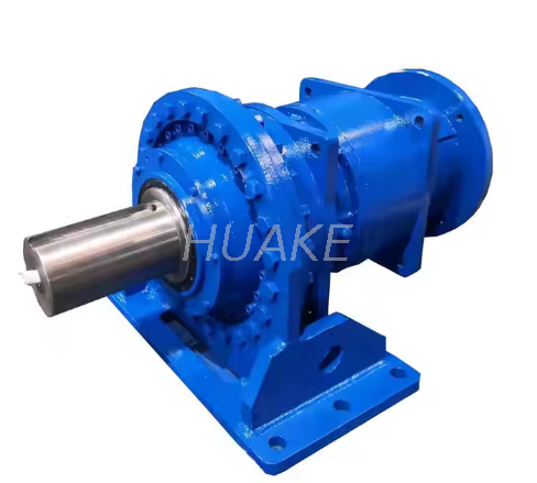
The primary reason engineers specify these units is their capability to handle massive loads. Because the gears are angled, they boast a higher contact ratio than straight-cut gears. This means that at any given moment, more teeth are actively engaged and sharing the mechanical burden. For instance, premium P-Series units routinely deliver nominal output torques ranging from 22 Nm up to a staggering 2000 Nm. This distributed load path allows the system to absorb sudden shock loads and sustain continuous demands without stripping teeth.
Backlash refers to the slight amount of clearance between mating gear teeth. In applications like multi-axis CNC machining or surgical robotics, even a fraction of a degree of excessive backlash leads to unacceptable positioning errors. Advanced designs are manufactured using multi-axis CNC grinding techniques to ensure perfect tooth profiles. Combined with the continuous engagement of the angled teeth, a high-end Precision Planetary Gearbox achieves backlash ratings under 3 arc-minutes, guaranteeing exact and repeatable positioning.
Acoustic performance is increasingly critical in modern manufacturing facilities. The sudden tooth impact of standard gears creates a distinct whining noise and micro-vibrations that resonate through a machine chassis. The gradual, sweeping engagement of angled teeth eliminates this harsh impact. As a result, the system operates smoothly, keeping factory floors significantly quieter and reducing vibration-induced wear on adjacent sensitive components.
Space is a premium commodity in industrial automation. Planetary designs inherently share mechanical loads across multiple gears. This distributed stress path allows engineers to drastically scale down internal components. You get the exact same power output as a bulky parallel-shaft unit, but in a fraction of the footprint. This empowers designers to build sleeker robotic arms and mobile platforms without sacrificing raw strength.
To assist procurement managers and technical buyers in their decision-making process, the following comparison evaluates this specific architecture against other common transmission methods.
| Feature | Angled Planetary System | Standard Parallel System | Worm Gear System |
|---|---|---|---|
| Design Architecture | Concentric and highly compact arrangement | Offset parallel shafts requiring a larger footprint | Right-angle shaft arrangement |
| Torque Density | Extremely High due to shared load across planet gears | Moderate to High | Low to Moderate |
| Mechanical Efficiency | Very High peaking at 97 percent | High ranging from 90 to 95 percent | Low ranging from 50 to 75 percent due to sliding friction |
| Backlash and Precision | Ultra-Low suitable for precision servo positioning | Moderate for standard industrial use | High and highly prone to wear over time |
| Operational Noise | Very Low due to gradual tooth engagement | Low to Moderate | Low but generates excessive thermal energy |
Specifically, you should opt for the planetary system when your application demands exact positioning, immense torque in a confined space, and continuous dynamic operation with a servo motor. Standard parallel units are better suited for driving large industrial machinery with standard alternating current motors where space is not a constraint. Meanwhile, worm gears remain the go-to choice when budget is the primary constraint, precision is irrelevant, or you specifically require a right-angle drive that self-locks to prevent back-driving.
In the realm of advanced robotics, particularly articulated robotic arms and delta robots, kinematic accuracy is non-negotiable. Imagine a robotic joint executing complex movements to weld an automotive chassis. It requires absolute repeatability. This demands a drive system that exhibits near-zero backlash. The angled teeth maintain constant contact, eliminating the micro-stutters associated with straight gears. Consequently, the transmission ensures the end-effector reaches its exact programmed coordinates.
Computer Numerical Control milling and turning centers operate under extreme dynamic loads. When a cutting tool engages with heavy metals like titanium, it generates severe radial forces and shock loads. If the transmission system lacks rigidity, these forces cause tool chatter, leading to poor surface finishes and accelerated tool wear. By distributing the load across multiple planet gears, the design provides exceptional torsional stiffness. This structural rigidity allows machines to maintain precise cutting depths and aggressive feed rates without deflection.
Modern packaging facilities operate on continuous production schedules. Conveyor systems and automated packaging machines require high-efficiency power transmission to minimize energy consumption. Standard worm gears often suffer from poor efficiency, sometimes losing up to forty percent of input power to heat. In contrast, premium planetary configurations routinely achieve mechanical efficiencies exceeding 95 percent. This high efficiency reduces the electrical load on servo motors, lowering overall operational costs.
Specifying a transmission unit for a bottom-of-funnel procurement decision requires a rigorous technical evaluation. Selecting an undersized unit leads to premature mechanical failure, while oversizing results in unnecessary capital expenditure and excessive inertia. Procurement managers should follow a systematic approach to match the gearbox to precise demands.
Torque capacity is the primary metric for selection. It is crucial to distinguish between continuous operating torque and intermittent peak forces. The nominal torque represents the continuous load required during standard operation. Your chosen unit must comfortably exceed this baseline.
Furthermore, during startup, rapid acceleration, or sudden deceleration, the system experiences torque spikes. The selected High Torque Reducer must possess a sufficient safety factor to handle these transient loads without suffering tooth root fatigue. In the event of an emergency stop, massive shockwaves travel through the drive train. Ensuring the unit can withstand these severe impacts is vital for longevity.
The gear ratio dictates the relationship between the motor input speed and the output speed, simultaneously multiplying the output torque. Single-stage reductions typically offer ratios from 3 to 10, while two-stage configurations expand this from 15 up to 100. Beyond basic speed reduction, ratio selection deeply impacts inertia matching.
In dynamic servo applications, the ratio of the load inertia to the motor inertia is critical for system stability. A gearbox reduces the reflected load inertia by the square of the gear ratio. Proper ratio selection ensures the servo motor can control the load smoothly without oscillation or tuning difficulties.
Backlash represents the lost motion between gear teeth upon reversing direction. Lower backlash equates to higher precision but generally increases manufacturing costs. Buyers should align this specification with actual application requirements to optimize return on investment.
For instance, standard precision ranging from 8 to 12 arc-minutes is highly economical and perfect for general conveyors. High precision ranging from 3 to 5 arc-minutes carries a moderate premium and suits pick-and-place automation. Ultra-precision at less than 3 arc-minutes requires a higher investment but is absolutely mandatory for advanced robotics.
While premium units are engineered for high durability, proactive maintenance is essential to achieve their maximum design life. When properly maintained, these units easily exceed 30,000 operational hours.
Tribology is central to mechanical longevity. Most modern precision units are supplied lubricated for life using advanced synthetic greases. These synthetic lubricants maintain their viscosity across a wide temperature spectrum and resist oxidation, requiring zero maintenance in standard environments.
However, heavy-duty industrial configurations operating under continuous high-speed or high-temperature conditions may utilize oil bath lubrication. For these units, engineers must strictly adhere to recommended oil change intervals. Operating with degraded lubricant breaks down the protective film between the gear teeth, leading to rapid metal-to-metal contact and micro-pitting.
Implementing condition-monitoring protocols allows maintenance teams to identify anomalies before they cause unplanned downtime. If an operator notices excessive surface temperature, it often points to overloading, excessive input speed, or degraded lubrication. An abnormal high-frequency whining noise usually indicates bearing wear or improper motor alignment.
Additionally, a sudden increase in backlash suggests wear on the gear tooth flanks or internal carrier deformation due to historical shock loads. Spotting these symptoms early allows for scheduled recalibration, safeguarding expensive servo motors from collateral damage.
The angled planetary transmission stands as an uncompromising engineering marvel. It provides exceptional power delivery for complex industrial systems, bridging the gap between brute strength and microscopic accuracy. Engineers consistently choose these units for their unparalleled torque density, zero-backlash capabilities, and whisper-quiet operation.
While the initial investment may surpass that of standard straight-cut gears, the reduced maintenance, high efficiency, and extended lifespan guarantee a vastly superior total cost of ownership. Proper selection ensures your equipment runs smoothly for years. Always match the gear ratio, backlash rating, and torque capacity to your specific motor application.
To explore highly customizable, industry-leading solutions for your next automation project, review the premium Planetary Gear Reducer models available at Huake Gearbox to meet your exact engineering specifications.
Yes, they can be driven in both forward and reverse directions with equal mechanical efficiency and precision. Unlike certain high-ratio worm systems which exhibit self-locking characteristics, this architecture allows for seamless bi-directional servo control. This makes them ideal for dynamic, rapid-reversing positioning applications.
Manufacturing angled gears requires highly advanced, multi-axis CNC machining to ensure perfect tooth profiles and precise incline angles. This complex manufacturing process increases production time and tooling costs. However, the result is a vastly superior unit that offers higher load-bearing capacity, smoother operation, and significantly reduced acoustic emissions.
Generally, yes. Most industrial units feature modular input designs. They come equipped with customizable motor adapter flanges and clamping collet mechanisms. These are engineered to precisely match the shaft diameters, pilot dimensions, and mounting bolt circles of all major international servo and stepper motor manufacturers, ensuring plug-and-play compatibility.
When correctly sized according to nominal and peak torque requirements, and operated within rated thermal limits, a high-quality unit exhibits exceptional longevity. It can easily surpass 20,000 to 30,000 hours of continuous operation. In many automated systems, the transmission actually outlasts the lifecycle of the primary machine it drives.
Extreme temperatures alter the viscosity of internal lubricants and can cause thermal expansion of metal components. Standard units operate comfortably between negative ten and ninety degrees Celsius. If your application falls outside this range, specialized synthetic lubricants and modified internal clearances are required to prevent premature bearing failure and maintain precision.
Yes, but input speed must be carefully monitored. While they easily handle standard servo motor speeds of 3000 to 4000 revolutions per minute, continuous operation at maximum rated speeds generates significant friction and heat. For applications requiring 24/7 high-speed input, engineers must select units optimized for thermal dissipation or employ external cooling methods.


