
- All
- Product Name
- Product Keyword
- Product Model
- Product Summary
- Product Description
- Multi Field Search


Views: 0 Author: Site Editor Publish Time: 2026-10-16 Origin: Site


Space is shrinking on the factory floor, yet torque demands are skyrocketing. As manufacturing equipment evolves, selecting the wrong powertrain component can quickly derail your operational efficiency and blow your engineering budget. If you specify an undersized drive today, you are practically guaranteeing premature mechanical failure down the line.
In the realm of mechanical power transmission, the planetary gear reducer has emerged as the definitive solution for high-torque, space-limited applications. While most system integrators understand the fundamental purpose of a speed reducer, deciding between traditional offset shaft designs and concentric configurations requires a deep dive into internal mechanics.
This comprehensive guide strips away the mystery surrounding these complex mechanisms. We will explore their core structural components, objectively weigh their mechanical advantages against their limitations, and provide a practical framework to help you specify the exact unit for your next automation project.
In industrial powertrain design, physical space constraints and extreme torque demands dictate the layout of a system. A planetary gear system, often referred to as an epicyclic gear train, is a highly engineered, inline mechanical device. Its primary job is to step down the rotational speed of a motor while simultaneously boosting its twisting force.
The mechanism earns its name from its structural resemblance to our solar system. The arrangement features secondary gears revolving around a central axis, creating a concentric power transmission method. This unique geometric configuration ensures that the input shaft and output shaft share the exact same rotational axis. Consequently, this streamlines machine integration and eliminates the need for bulky offset mounting plates.
To fully grasp how this mechanism withstands millions of cycles under heavy load, you must look inside the casing. Each component is typically CNC-machined from high-strength alloy steels. They are then subjected to advanced heat treatments, such as gas carburizing up to 60 HRC, to resist severe operational fatigue.
The fundamental working principle relies on simultaneous, multi-point gear meshing. When you power up an AC induction or servo motor, the central sun gear begins to rotate at high velocity. Because this central gear meshes directly with the surrounding planet gears, its rotation forces them to spin on their individual axes.
However, the external teeth of these planet gears are also locked into the internal teeth of the stationary ring gear. Since the ring gear cannot move, the planet gears are forced to walk or orbit along the inner circumference of the housing. As they travel, they drag the heavy planetary carrier with them. Ultimately, the carrier rotates in the same direction as the input shaft but at a vastly reduced speed.
The true engineering brilliance of these systems lies in their load distribution. In a standard parallel-shaft gearbox, the entire mechanical load is concentrated on a single gear tooth contact point. If a sudden shock load exceeds the shear strength of that specific tooth, catastrophic failure is imminent.
By contrast, a planetary system splits that exact same load across multiple planet gears. If your system utilizes three planets, the mechanical stress at any given millisecond is divided across three simultaneous mesh points. This shared burden drastically reduces the stress on individual teeth. Therefore, the mechanism can transmit immense radial and axial forces without requiring a massive cast-iron housing.
System integrators do not specify an Industrial Planetary Drive merely to connect two shafts. They deploy it to fundamentally alter the dynamic characteristics of a powertrain. The integration of this device serves three primary mechanical purposes.
Electric motors operate most efficiently at high speeds, often between 1,500 and 4,000 RPM. Yet, a packaging conveyor or a robotic joint requires much slower, deliberate movements. The gear system acts as a mechanical bottleneck. The specific reduction ratio dictates the final output. For instance, feeding a 3,000 RPM motor into a 10:1 planetary reducer yields a highly controlled, usable output of 300 RPM.
In mechanical physics, power is the product of torque and angular velocity. Assuming minimal efficiency losses, as the rotational speed decreases, the torque increases proportionately. Precision units often operate at up to 97 percent efficiency. This inverse relationship is critical. It allows a relatively compact, energy-efficient servo motor to generate enough raw twisting force to lift a massive payload or drive a heavy continuous-process extruder.
Often overlooked by novice builders, inertia matching is the secret to stable automation. Inertia is a load's natural resistance to changes in velocity. In highly dynamic applications requiring rapid starts, sudden stops, and exact positioning, a mismatch between a heavy load's inertia and the motor's rotor inertia causes instability. The system will overshoot and fail to tune properly. A planetary reducer lowers the reflected load inertia back to the motor by the square of the gear ratio. This ensures crisp, highly responsive motion control.
From a global manufacturing perspective, the transition towards smart factories is radically altering power transmission standards. We are seeing a massive shift driven by the electric vehicle manufacturing boom and the rapid deployment of collaborative robots. Engineers are no longer satisfied with raw power alone; they face strict spatial limitations.
Recent market data indicates a surging demand for miniaturized, high-torque density components. As automated guided vehicles become flatter to slide under transport pallets, and robotic joints require tighter integration, the physical footprint of a drive becomes a primary constraint. Consequently, relying on concentric, low-backlash gearing systems has transitioned from a premium upgrade to an absolute baseline requirement across the automation sector.
While these systems represent a pinnacle of modern mechanical engineering, they are not a universal cure-all. An objective evaluation of their strengths and physical limitations is necessary to avoid costly over-engineering.
When engineering a heavy-duty powertrain, the most frequent debate is choosing between a standard helical gear unit and a planetary reducer. Both step down speed and multiply torque, but their architectures cater to vastly different industrial realities.
Helical gearboxes utilize parallel or right-angle shaft configurations. Because the power is transferred point-to-point across separate shafts, they inherently require larger, bulkier cast-iron housings. This offset design takes up significant lateral space. Conversely, the planetary unit's inline design allows it to be perfectly cylindrical. It essentially acts as a direct extension of the motor's geometry.
Helical gears are legendary for their smooth, quiet operation. They are exceptional for continuous, one-directional heavy operations, much like a massive mining conveyor running around the clock. However, achieving extremely low backlash in standard helical units is difficult and cost-prohibitive.
Planetary gears dominate in precision. Because the gears are tightly constrained within the rigid ring gear, they can be engineered with ultra-low backlash. Precision models often feature less than 3 arc-minutes of play. Therefore, a High Torque Gearbox with a concentric layout is the definitive choice for reversing servo applications where exact positioning is critical.
| Feature / Dimension | Planetary Gear Reducer | Helical Gear Unit |
|---|---|---|
| Shaft Alignment | Coaxial and Inline | Parallel or Right-Angle |
| Torque Density | Extremely High | Moderate |
| Backlash Precision | High Precision under 5 arc-minutes | Standard Precision with higher physical play |
| Load Distribution | Shared across multiple planet gears | Concentrated on a single gear mesh point |
| Initial Cost | Higher due to machining precision | Lower to Moderate |
Because of their unique combination of compactness, precision, and brute strength, these systems are deployed across the most demanding industrial sectors.
In modern packaging lines and automated warehousing, space is at an absolute premium. Planetary reducers provide the low backlash required for the exact positioning of robotic arms and delta robots. They ensure that automated systems can perform repetitive, high-speed tasks with sub-millimeter accuracy without vibrating out of calibration.
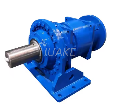
In extreme heavy-duty sectors, torque is non-negotiable. Specialized, large-scale models like a P Series Gearbox are frequently integrated into bucket wheel excavators, aggregate crushers, and industrial mixers. In these harsh environments, the gearbox must withstand massive shock loads and continuous radial forces. This is a task made possible only by the distributed load design of the planetary carrier.
Selecting the correct unit prevents premature mechanical failure, protects against motor burnout, and optimizes overall machine performance. Follow this structured engineering approach to specification.
Start by calculating the required output speed based on your machine's ideal cycle time. Divide your motor's nominal RPM by this target speed to find the exact gear ratio. Next, calculate the continuous running torque and the peak acceleration torque. Ensure the drive you select has a nominal torque rating that comfortably exceeds your continuous load. Always factor in a Service Factor based on daily operating hours and potential shock loads.
Backlash is measured in arc-minutes, which is one-sixtieth of a degree. For standard power transmission, such as turning a simple material belt, standard backlash between 8 and 15 arc-minutes is perfectly acceptable and cost-effective. However, for precise CNC applications where reversing direction could cause compounding positioning errors, you must specify a precision-grade unit with reduced backlash of 1 to 3 arc-minutes.
Evaluate the physical operating environment closely. If the equipment will be exposed to fine dust or high-pressure water washdowns, specify an appropriate IP65 or IP67 rating. Determine whether the unit requires standard grease lubrication or oil-bath lubrication for better continuous heat dissipation. Finally, double-check that the input flange and shaft coupling are perfectly matched to your specific servo or stepper motor dimensions to avoid radial misalignment during installation.
The planetary gear reducer remains an unmatched mechanical solution for applications demanding high torque, a compact physical footprint, and uncompromising precision. By distributing loads across multiple internal gears, it allows engineers to push the boundaries of machine design. You can build smaller, faster, and much stronger equipment.
However, successful integration requires balancing this incredible power density against initial costs and thermal management. By carefully calculating your required ratios, understanding your backlash tolerances, and evaluating environmental factors, you can ensure decades of reliable power transmission. When you are ready to upgrade your powertrain or need precise load calculations, explore the specialized engineering solutions and robust product lineups available at Huake Gearbox to find the exact match for your industrial needs.
Depending on the applied load, daily operating hours, and maintenance of lubrication, a high-quality unit can last anywhere from 10,000 to over 30,000 hours of continuous operation. Proper initial sizing and avoiding severe, uncalculated shock loads will significantly extend this lifespan.
Yes, they can generally be back-driven. However, high-ratio multi-stage units possess significant internal friction that can strongly resist back-driving. This is a critical consideration if your machine requires a manual override or a safety release mechanism.
Their highly compact, nested design means there is very little external surface area to dissipate the heat generated by the friction of multiple internal gears operating simultaneously. Proper synthetic lubrication and strictly adhering to the manufacturer's rated input speeds are vital to mitigate excessive thermal buildup.
A single-stage reducer uses one set of planetary gears and typically offers reduction ratios up to 10:1. A two-stage unit connects two sets in series, where the carrier of the first stage drives the sun gear of the second stage. This multiplies the ratio, offering massive reductions up to 100:1 for extreme low-speed, high-torque applications.
Many modern, compact industrial drives are factory-sealed and lubricated for life with high-performance synthetic grease. These require zero maintenance. However, massive heavy-duty models utilizing oil baths will require periodic oil changes and seal inspections according to the manufacturer's strict maintenance schedule.
The basic gear ratio for a single-stage planetary system where the ring gear is stationary is calculated by dividing the number of teeth on the ring gear by the number of teeth on the sun gear, and then adding one. For example, if the ring gear has 60 teeth and the sun gear has 15 teeth, the ratio is 60 divided by 15 plus 1, resulting in a 5:1 reduction ratio.
Due to the balanced load distribution and rolling action of the gear teeth, these systems are highly efficient. A high-quality, single-stage planetary reducer typically operates at 96 to 98 percent efficiency. Multi-stage units will see a slight drop in efficiency, usually operating around 93 to 95 percent due to the added friction of the secondary gear sets.


