
- All
- Product Name
- Product Keyword
- Product Model
- Product Summary
- Product Description
- Multi Field Search


Views: 0 Author: Site Editor Publish Time: 2026-07-31 Origin: Site


In industrial drive systems, a gear reducer is not selected only by torque or speed ratio. Shaft layout is also important. The position of the motor, reducer and driven machine can directly affect installation space, alignment, coupling design, maintenance access and long-term transmission stability.
An inline helical gear reducer is often selected when the motor shaft and output shaft need to remain on the same centerline. This layout is useful when the machine requires straight-line power transmission, compact radial width, smooth torque output and efficient speed reduction.
In many industrial applications, inline reducers are used for pumps, conveyors, mixers, packaging machinery, food processing equipment and general drive systems. However, an inline layout is not always the best option. If the machine needs a 90-degree direction change, an offset shaft arrangement or a hollow shaft mounting structure, a parallel shaft or right-angle reducer may be more suitable.
For different industrial layouts, HUAKE’s Helical Gear Reducers include inline, parallel shaft and right-angle configurations to support different torque, speed and installation requirements.
This article explains when to choose an inline helical gear reducer, when another reducer layout may be better, and what selection factors should be checked before final model confirmation.
An inline helical gear reducer is a strong choice when the drive system needs straight-line shaft alignment, efficient torque transmission, smooth operation and a compact radial layout.
Key points include:
Inline reducers are suitable when input and output shafts need to stay aligned.
Inline and coaxial reducer layouts are often closely related in industrial gearbox selection.
Helical gear teeth support smooth meshing, efficient transmission and stable torque output.
Inline layouts are useful for pumps, conveyors, mixers, packaging machinery and general industrial drives.
Inline reducers may not be suitable when the machine needs a 90-degree direction change.
Parallel shaft reducers may be better when the input and output shafts must be offset.
Gear ratio, output torque, input speed, mounting position and service factor must be checked.
Final selection should consider both mechanical performance and installation layout.
In short, an inline helical gearbox is suitable when the machine layout favors straight-line power transmission and the reducer can meet the required torque, speed and duty conditions.
An inline helical gear reducer is a speed reduction unit that uses helical gears and arranges the input and output shafts along the same axis or centerline. In many industrial gearbox discussions, “inline” and “coaxial” are closely related terms. They usually describe a reducer structure where power flows in a straight line from the motor to the driven machine.
The helical gear design provides smooth tooth engagement. Compared with spur gears, helical gears engage gradually, helping reduce vibration and noise. This makes inline helical reducers suitable for machinery that requires stable rotation and reliable torque transmission.
A typical inline helical reducer is used to:
Reduce motor speed
Increase output torque
Maintain shaft alignment
Save radial installation space
Improve motion stability
Support continuous industrial operation
Because of these characteristics, inline helical reducers are widely used in industrial transmission systems where compact, efficient and aligned drive layouts are required.
Choosing an inline helical reducer depends on the machine layout and operating requirements. It is generally suitable in the following situations.
The most direct reason to choose an inline reducer is shaft alignment. If the motor, reducer and driven shaft are arranged on the same centerline, an inline helical gear reducer can simplify the transmission layout.
This is useful when the machine design requires direct coupling between the motor, reducer and driven equipment.
Inline reducers allow power to move in a straight path. This reduces layout complexity and may simplify installation.
Straight-line transmission is common in pumps, rollers, conveyors, mixers and general drive units where the equipment does not require a change in shaft direction.
An inline reducer often keeps the transmission width relatively narrow. If the machine has limited side space but enough axial length, an inline layout can be practical.
However, if axial space is limited, a parallel shaft or right-angle reducer may be better.
Helical gear transmission is generally efficient. For industrial equipment that runs frequently or continuously, high efficiency helps reduce energy loss and heat generation.
This is one reason why inline helical gear reducers are commonly used in production equipment where stable operation and energy efficiency both matter.
The smooth meshing of helical gears helps deliver stable torque. This is useful for machines that need consistent motion, lower vibration and reduced noise.
Applications such as packaging lines, food processing machines and pump systems often benefit from stable torque transmission.
An inline layout can make mechanical alignment easier when the motor and driven shaft already share the same axis. It may also simplify inspection, coupling alignment and maintenance access, depending on the machine design.
| Condition | Why Inline Helps |
|---|---|
| Motor and machine are on the same axis | Simplifies coupling and alignment |
| Straight-line drive path is preferred | Reduces layout complexity |
| High efficiency is required | Helical gears support efficient transmission |
| Stable torque output is needed | Smooth gear engagement supports reliable operation |
| Compact radial width is needed | Inline reducer keeps side width relatively narrow |
| Maintenance access is important | Inline layout may simplify inspection |
| Low vibration is required | Helical tooth contact improves running smoothness |
| General industrial drive is needed | Inline reducers fit many standard drive layouts |
An inline helical gear reducer is useful, but it is not suitable for every installation. In some cases, another reducer layout may fit better.
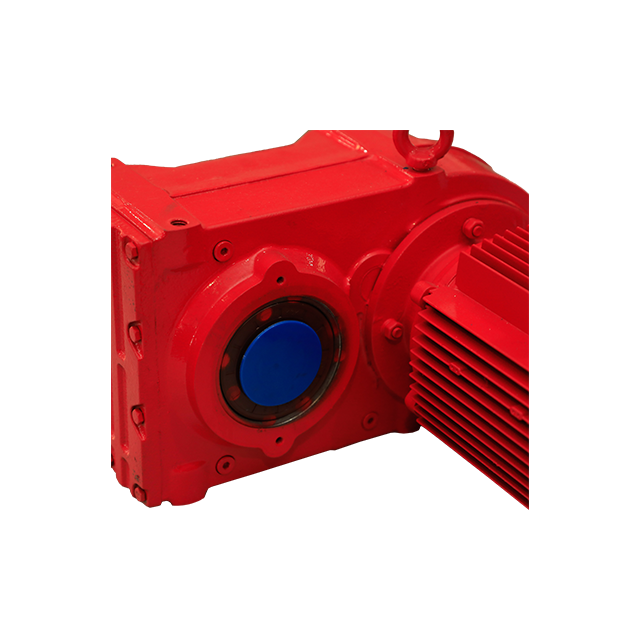
If the motor and driven shaft are arranged at right angles, an inline reducer will not solve the direction change. A right-angle gear reducer is usually more suitable.
If the input and output shafts must be parallel but not aligned on the same centerline, a parallel shaft helical reducer may be more practical.
If your machine requires an offset shaft arrangement rather than an inline layout, the F Series Parallel Shaft Helical Gear Reducer may be more suitable for compact side-by-side transmission.
Inline reducers may require more space along the shaft direction. If the equipment has limited axial length, a parallel shaft or right-angle design may allow a more compact layout.
Some conveyors and driven machines use hollow shaft mounting or shaft-mounted installation. In these cases, a different reducer structure may be more suitable.
Some machines are designed around side mounting or space routing. If the reducer must be installed beside the driven machine instead of directly in line, inline may not be the best option.
| Reducer Type | Shaft Layout | Best Use |
|---|---|---|
| Inline helical gear reducer | Input and output shafts aligned | Straight-line power transmission |
| Parallel shaft helical reducer | Shafts are parallel but offset | Compact side-by-side layouts |
| Right-angle gear reducer | Input and output turn 90 degrees | Direction change in tight layouts |
| Shaft-mounted reducer | Reducer mounts directly on driven shaft | Conveyor and material handling systems |
| Customized reducer | Non-standard shaft or mounting design | Special machinery or limited installation space |
The best layout depends on the physical arrangement of the machine. A reducer that is mechanically strong may still be unsuitable if the shaft direction or mounting position does not fit the equipment.
Motor and Driven Machine on Same Centerline?
        ↓
Need Straight-Line Power Transmission?
        ↓
Enough Axial Installation Space?
        ↓
Required Torque and Ratio Fit Inline Reducer?
        ↓
Mounting Position and Coupling Confirmed?
        ↓
Choose Inline Helical Gear Reducer
This flow chart shows the basic selection logic. If any step does not match the equipment layout, another reducer type should be considered.
Pumps often require stable speed and continuous rotation. An inline helical gearbox can fit pump systems where the motor and pump shaft are arranged in a straight line.
Some conveyor drive systems can use inline reducers when the motor and driven shaft are aligned. However, if the conveyor requires offset shaft installation, a parallel shaft reducer may be more suitable.
Mixers and agitators may use inline reducers when straight-line torque transmission is required. Selection should consider material viscosity, starting torque and operating hours.
Packaging machines often need compact design, stable speed and low vibration. Inline helical reducers can support smooth movement in filling, sealing, labeling and conveying systems.
Food processing machines may require stable speed, low noise and easy maintenance access. Inline helical reducers can be suitable when the installation layout supports straight-line transmission.
Inline reducers are also used in general industrial machines, including rollers, fans, small processing machines and equipment that requires standard motor-reducer coupling.
| Application | Why Inline May Fit | Key Selection Focus |
|---|---|---|
| Pumps | Motor and pump shaft may align naturally | Speed, torque, coupling alignment |
| Conveyors | Suitable when drive shaft is in line | Torque, ratio, mounting space |
| Mixers | Supports straight-line torque transmission | Starting torque and load fluctuation |
| Packaging machines | Smooth and compact transmission | Low vibration and stable speed |
| Food machinery | Stable operation and easier access | Clean layout and maintenance |
| Fans and rollers | Direct drive path | Output speed and bearing load |
| General machinery | Standard motor-reducer structure | Ratio, mounting position, environment |
Gear ratio determines output speed. The reducer should match the required machine speed based on motor input speed and driven equipment demand.
A ratio that is too low may make the machine run too fast. A ratio that is too high may make the machine too slow or increase reducer size unnecessarily.
Output torque must meet the actual load requirement. Users should consider both normal running torque and peak torque. For high-load or variable-load applications, torque reserve is important.
The motor speed must be compatible with the reducer input rating. Excessive input speed may increase noise, heat and lubrication demand.
Service factor reflects operating hours, load type, starts and stops, shock load and application severity. Machines running long hours or under variable load usually require more careful service factor evaluation.
Mounting position affects oil distribution, installation convenience and space layout. Before choosing an inline helical gear reducer, confirm whether the machine needs foot-mounted, flange-mounted, horizontal or vertical installation.
Check how the reducer connects with the motor and driven equipment. Coupling type, shaft diameter, keyway, flange size and alignment tolerance should be confirmed.
A reducer used for occasional operation has different requirements from one used in continuous production. Long operating hours increase the importance of lubrication, heat control and bearing life.
Dust, humidity, temperature, outdoor exposure and chemicals can affect seals, lubricant and reducer service life. Environmental conditions should be considered before selection.
For coaxial transmission layouts, the R Series Helical Gear Hardened Gear Reducer can be considered when compact inline installation, stable torque output and reliable speed reduction are required.
| Selection Factor | What to Check |
|---|---|
| Shaft layout | Whether input and output shafts need to align |
| Gear ratio | Required output speed |
| Output torque | Normal load and peak load torque |
| Input speed | Motor rpm and reducer input rating |
| Motor power | Whether power matches torque demand |
| Mounting position | Foot, flange, horizontal or vertical mounting |
| Service factor | Duty cycle, starts/stops and shock load |
| Coupling | Motor-reducer-machine connection |
| Axial space | Whether enough length is available |
| Radial space | Whether narrow side width is required |
| Lubrication | Oil level, viscosity and maintenance interval |
| Environment | Dust, humidity, heat and chemicals |
| Maintenance access | Inspection, oil change and alignment space |
Avoid these mistakes when choosing an inline helical gear reducer:
Selecting inline layout without checking shaft alignment
Choosing ratio without checking output torque
Ignoring axial installation space
Ignoring mounting position
Assuming inline is always better than parallel shaft or right-angle
Ignoring service factor in continuous-duty applications
Using the wrong reducer for shock-load machinery
Ignoring coupling dimensions
Ignoring lubrication and maintenance access
Not checking working temperature, dust or humidity
A correct selection should balance layout, torque, speed, installation and environment.
HUAKE provides multiple helical reducer configurations for industrial transmission systems. For inline or coaxial layouts, the R Series is often the most direct direction. It can support applications where the motor, reducer and driven machine need stable straight-line power transmission.
For offset shaft layouts, the F Series may be more suitable. For right-angle power transmission, other reducer configurations should be considered depending on the machine structure.
HUAKE can help users evaluate:
Shaft layout
Gear ratio
Output torque
Motor power
Input speed
Mounting position
Load type
Duty cycle
Installation space
Working environment
Maintenance requirements
The right reducer should not be selected by structure alone. It should be matched to both mechanical load and physical installation.
An inline helical gear reducer is a good choice when an industrial machine requires straight-line power transmission, aligned input and output shafts, stable torque output, efficient speed reduction and compact radial installation. It is commonly used in pumps, packaging machinery, food processing equipment, conveyors, mixers and general industrial drives.
However, inline layout is not always the best option. If the machine requires a 90-degree direction change, offset shaft arrangement, hollow shaft mounting or very limited axial space, a parallel shaft or right-angle reducer may be more suitable.
Before choosing an inline helical gearbox, users should check gear ratio, output torque, input speed, shaft layout, mounting position, service factor, coupling method, operating hours, working environment and maintenance access.
Need help selecting the right inline reducer layout? Contact HUAKE for an inline helical gear reducer solution based on your motor power, input speed, output torque, gear ratio, shaft layout, mounting position and operating environment.
An inline helical gear reducer is a reducer that uses helical gears and arranges the input and output shafts along the same centerline or axis. It is used for straight-line power transmission.
In many industrial gearbox discussions, inline and coaxial are closely related. They usually refer to a layout where the input and output shafts are aligned, but exact naming may vary by manufacturer.
You should choose an inline helical gear reducer when the motor and driven machine need to stay on the same centerline and the application requires efficient, stable straight-line torque transmission.
An inline reducer may not be suitable when the drive needs a 90-degree direction change, offset shaft arrangement, hollow shaft mounting or very limited axial space.
An inline reducer has input and output shafts aligned on the same centerline. A parallel shaft reducer has input and output shafts that are parallel but offset from each other.
An inline reducer transmits power in a straight line. A right-angle reducer changes power direction by 90 degrees, which is useful in space-limited layouts.
Common applications include pumps, conveyors, mixers, packaging machinery, food processing equipment, fans, rollers and general industrial drive systems.
You should check gear ratio, output torque, input speed, mounting position, service factor, shaft connection, axial space, operating hours and working environment.
It can be suitable for high-load applications if the reducer is correctly selected with enough output torque, service factor, bearing support and proper lubrication.
Yes. HUAKE can help evaluate shaft layout, motor power, input speed, output torque, gear ratio, mounting position and operating environment to recommend a suitable inline helical gear reducer.


