
- All
- Product Name
- Product Keyword
- Product Model
- Product Summary
- Product Description
- Multi Field Search


Views: 0 Author: Site Editor Publish Time: 2026-10-14 Origin: Site


Look inside any automated robotic arm, precision conveyor belt, or heavy-duty material handler. You will find a gear motor driving the system. An electric motor paired with a gear reducer forms a highly efficient unit. It multiplies rotational force while simultaneously reducing shaft speed. However, specifying the wrong unit leads to catastrophic system failures, extensive operational downtime, and severely wasted capital budgets.
The purpose of this engineering guide is to provide a comprehensive methodology for proper gear motor selection. By following empirical guidelines and objective calculations, engineers, procurement specialists, and system designers can match exact technical specifications to their project needs. This rigorous approach ensures long-term reliability and seamless operational efficiency.
The process of specifying a drive unit goes far beyond simply matching physical dimensions. It is fundamentally about aligning electromechanical capabilities with rigorous application demands. Industry analysts observe a definitive shift toward compact high-torque-density drive systems. Driven by the rapid expansion of automated warehousing and smart manufacturing, engineers are moving away from oversized legacy systems. Today, the focus is squarely on energy optimization and seamless integration with predictive maintenance sensors. Consequently, making an accurate data-driven choice impacts three primary areas of your operation.
System Reliability
The primary objective of rigorous selection is maximizing the Mean Time Between Failures. When a reducer and motor are perfectly matched to their payload, they operate comfortably within their thermal and mechanical limits. This harmony prevents premature wear and tear on the internal copper windings, steel bearings, and the driven equipment itself. Ultimately, proper specification mitigates the risk of sudden gear tooth fracture or catastrophic insulation breakdown.
Cost Efficiency
Financial efficiency is heavily dependent on accurate sizing. Over-sizing a motor leads to unnecessary initial capital expenditure, increased structural support requirements, and ongoing energy waste due to poor power factor at partial loads. In contrast, under-sizing inevitably leads to frequent thermal overloads, repetitive maintenance costs, and crippling production downtime.
Performance Optimization
In applications requiring high precision like packaging machinery or automated guided vehicles, precise selection ensures fluid operation. It guarantees correct operational speeds, exact positioning, and the ability to handle dynamic load shifts without stalling or stuttering during critical production phases.
Before running any mathematical equations, you must establish the baseline operational context of the machine. A drive unit that hums along perfectly in a climate-controlled pharmaceutical laboratory will quickly seize up and fail in a dusty high-vibration stone quarry.
Not all payloads interact with a motor in the same way. Specifically, the nature of the mechanical resistance dictates the required robustness of the internal gearing.
The duty cycle defines exactly how often the motor will operate versus how long it rests. This directly impacts thermal dissipation.
The surrounding environment dictates the physical protection the unit requires to survive.
The technical heart of equipment specification relies on objective physics and mechanical formulas. Guessing is not an engineering strategy. Never rely on estimations when empirical calculations are readily available.
Rotational force delivered by the gearbox shaft to the driven machine is the absolute most critical parameter. Accurately calculating the Output Torque determines whether the mechanism can physically move the payload from a standstill. To specify this correctly, you must evaluate two distinct values.
First, consider the running torque. This is the continuous force required to keep the load moving at a steady operational speed. Second, evaluate the breakaway starting torque. This represents the initial surge of force required to overcome static friction and inertia to initiate movement. This starting value is typically much higher than running torque.
Standard Formula in lb-in: Torque = Horsepower × 63,025 / RPM
This parameter defines the mechanical advantage provided by the internal gear set. The Gear Ratio is the mathematical relationship between the high-speed input from the electric motor and the low-speed high-torque output of the reducer shaft.
Standard Formula: Gear Ratio = Motor Input Speed / Required Output Speed
For instance, if your application requires a final conveyor belt drive to run at exactly 50 RPM, and you are integrating a standard AC motor with a base speed of 1750 RPM, the calculation is straightforward. Dividing 1750 by 50 equals 35. Therefore, you would require a gear ratio of 35:1.
Once rotational force and speed are firmly established, you can determine the necessary Motor Power measured in Horsepower or Kilowatts. Matching the exact power requirement ensures the unit operates highly efficiently without drawing excess current or overheating during standard shifts.
Standard Formula in HP: HP = Torque × RPM / 63,025
Furthermore, the electrical voltage must align perfectly with your facility's available power supply. Heavy industrial environments typically utilize 3-phase AC power for massive torque delivery. Meanwhile, mobile robotics or precision medical devices often rely on low-voltage DC power for portability and safety.
With your calculations complete and verified, the next phase is selecting the specific electromechanical architecture that best delivers those numbers. The internal geometry of the gear teeth significantly impacts mechanical efficiency, physical footprint, and overall load capacity.
| Gearbox Technology | Transmission Efficiency | Structural Footprint | Ideal Industrial Application |
|---|---|---|---|
| Helical Gears | Very High over 95% | Moderate Inline or Parallel | Continuous-duty industrial conveyors and heavy extruders. |
| Planetary Gears | High over 90% | Highly Compact Cylindrical | Precision servo applications and heavy-duty robotics. |
| Worm Gears | Lower 50% to 85% | Space-saving Right Angle | Cost-effective systems requiring self-locking properties. |
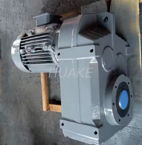
When spatial constraints meet heavy load demands, specialized configurations become necessary. Integrating a unit like the F-Series Helical Gear Motor FA107 offers a parallel shaft design that significantly reduces the mechanical footprint while maintaining high transmission efficiency for heavy automation equipment.
Even the most perfectly calculated drive unit is utterly useless if it cannot physically fit into your machine's framework. Spatial constraints dictate the required Mounting Type. This structural configuration must be decided early in the mechanical design phase to avoid expensive structural redesigns.
The physical orientation of the unit directly affects internal fluid dynamics. For instance, a unit designed for horizontal mounting may suffer from severe bearing starvation if flipped vertically. The lubricating oil will pool at the bottom, leaving upper gears dry. Always specify the exact mounting orientation so the manufacturer can correctly position the oil fill, drain, and breather plugs. Additionally, inline configurations are suited for long narrow spaces, while right-angle configurations effectively solve tight depth-constraint issues.
Even seasoned mechanical engineers can overlook subtle variables that inevitably lead to premature mechanical failure. Avoiding these standard pitfalls is critical for ensuring system longevity.
When a pulley, chain sprocket, or heavy gear is mounted directly to the gearbox output shaft, it exerts a severe perpendicular force known as a radial or overhung load. If this side-load exceeds the internal bearing capacity of the gearbox, the shaft will physically deflect. This deflection leads to rapid bearing cage failure and blown oil seals. Always verify the manufacturer's overhung load ratings against your actual physical setup.
Heat remains the ultimate adversary of electromechanical devices. When engineers fail to account for high ambient temperatures, the results are predictable. Gearbox lubrication rapidly degrades and winding insulation melts. Therefore, if the operating environment frequently exceeds 40 degrees Celsius, the motor must be thermally derated. Alternatively, external forced-air cooling mechanisms must be seamlessly integrated into the machine design.
A frequent error is matching a 10 Nm application load to a motor rated for exactly 10 Nm. Standard catalog nameplate ratings reflect performance under ideal continuous laboratory conditions. Real-world applications often involve sudden shock loads, jams, and frequent starts. Failing to apply an appropriate Service Factor based on the application's actual harshness will result in an under-sized failure-prone drive system.
Once the technical specifications are rigorously defined on paper, the final critical step is physical procurement. The quality of the raw materials, machining tolerances, and assembly processes dictate whether the unit will last for ten months or ten years.
Sourcing from a manufacturer with a proven track record ensures that the catalog specifications actually match real-world performance. High-quality manufacturers provide comprehensive testing data, robust warranties, and direct engineering support to verify your complex calculations. For engineers and procurement teams looking for proven reliability, exploring specialized solutions from established providers like Huake Gearbox ensures access to a diverse catalog of industrial-grade components. Working with established industry experts ensures that your engineered systems operate safely, efficiently, and continuously.
You must never guess your motor specifications. Always calculate your exact system requirements meticulously. Defining the operational load profile ensures a successful mechanical integration from day one. By accurately matching the output torque, determining the optimal speed reduction ratio, and choosing the correct electrical power and mounting configuration, you guarantee a highly successful project execution. If uncertainties arise during the mechanical design phase, consulting with dedicated engineering experts will help you find the perfect long-lasting fit for your specific operational demands. Visit Huake Gearbox to explore a comprehensive range of industrial gear motors tailored to your exacting project requirements.
If the rotational force is insufficient, the motor will immediately stall because it cannot overcome the mechanical resistance of the load. This stall condition causes a massive spike in electrical current, leading to rapid overheating, insulation breakdown, and eventual motor burnout, resulting in complete system failure.
First, determine the precise desired output speed of your driven machine. Next, divide the electric motor's base input speed by that desired output speed. The resulting number is your required reduction ratio.
Yes, significantly. Incorrect mounting orientations can lead to improper lubrication flow within the gearbox casing. If gears and upper bearings are starved of oil due to gravity pulling the lubricant away from them, it causes excessive friction and metal-on-metal wear, drastically reducing the operational lifespan of the unit.
No. You must verify that the AC motor is specifically inverter-duty rated. Running a standard non-inverter motor at very low speeds via a VFD slows down its shaft-mounted cooling fan. Without adequate airflow, the motor will rapidly overheat and fail during prolonged low-speed operation.
A service factor is an essential engineering safety multiplier applied to a motor's base power or torque rating. It accounts for real-world operational stresses such as heavy shock loads, frequent starting and stopping, or extreme environmental conditions. Applying this factor ensures the motor is adequately sized to survive harsh non-ideal duties.
You calculate the service factor by evaluating the machine's daily operating hours, the type of load it drives, and the frequency of starts and stops. Manufacturers provide specific service factor tables in their catalogs. You simply cross-reference your application type against your daily usage hours to find the correct multiplier, typically ranging from 1.0 to 2.0 or higher.
A standard electric motor typically operates at high speeds with relatively low torque. A gear motor is a fully integrated assembly combining that standard electric motor with a mechanical gear reducer. This integration allows the unit to significantly lower the output speed while proportionally multiplying the output torque, making it ideal for moving heavy industrial loads.


