
- All
- Product Name
- Product Keyword
- Product Model
- Product Summary
- Product Description
- Multi Field Search


Views: 0 Author: Site Editor Publish Time: 2026-08-16 Origin: Site


While the internal 90-degree gear transition solves severe spatial constraints, transferring high torque efficiently depends entirely on how you anchor the unit to the machine frame. Many designers underestimate this crucial connection point. Incorrect mounting inevitably causes mechanical misalignment. This error introduces massive radial stress on internal bearings. Ultimately, poor installation drastically reduces the lifecycle of your entire drive assembly. You simply cannot afford these unpredictable mechanical failures on the factory floor.
This article equips engineers and procurement teams with a practical decision-making framework. We will help you evaluate foot, flange, and shaft-mounting configurations accurately. You will learn to analyze these specific setups based on realistic load demands, tight space constraints, and ongoing maintenance accessibility. Mastering these structural strategies ensures your industrial systems run longer and smoother under peak stress.
Foot mounting offers the highest rigidity for heavy shock loads but requires precise shimming to avoid "soft foot" distortion.
Flange mounting eliminates baseplate requirements and simplifies alignment, but demands tight machining tolerances on the driven machine face.
Shaft mounting (with a torque arm) is the optimal choice for a compact bevel gear reducer in conveyor systems, absorbing shock while minimizing structural footprint.
Orientation matters: The chosen mounting style directly dictates oil levels, breather plug placement, and lubrication flow, requiring specification prior to ordering.
Premature bearing failure rarely happens due to internal manufacturing flaws. Shaft fatigue almost never originates from poor gear hobbing. These critical failures are most often the direct result of external mounting misalignment. Unmanaged overhung loads bend the output shafts. When you mount a drive incorrectly, you introduce parasitic loads into the system. These unintended forces push roller bearings past their rated limits. The internal gear mesh loses optimal contact. Heat builds up rapidly inside the casing. You will experience catastrophic failure if you ignore the structural foundation.
A successful mounting strategy must achieve three specific technical objectives. First, it must guarantee total immobility under peak starting torque. The housing cannot shift when the motor activates. Second, the mount must ensure zero induced deflection on the output shaft. The connection must remain perfectly neutral. Third, you must maintain highly accessible points for routine maintenance. Mechanics need clear pathways for oil changes. They must view condition monitoring sensors easily. If maintenance is difficult, technicians will skip it.
You must adhere strictly to established engineering standards. We highly recommend following AGMA and ISO alignment tolerances during installation. Original equipment manufacturers base their operational guarantees on these rigid metrics. Validating your OEM warranties requires documented proof of proper alignment. Precision laser alignment protects internal components. It ensures the theoretical bearing lifespan matches reality. Ignoring these standard tolerances will void your warranty coverage immediately.
The foot-mounted mechanism involves bolting the housing directly to a structural baseplate. The cast-iron body features precision-machined support feet. You secure these heavy feet using industrial-grade fasteners. A standard helical bevel gearbox performs exceptionally well here. This setup is best for high-torque, heavy-duty applications. Large industrial mixers and heavy plastics extruders rely on foot mounts. The massive structural frame absorbs intense mechanical vibration safely. Heavy shock loads require this level of foundation rigidity. The ground absorbs the kinetic energy.
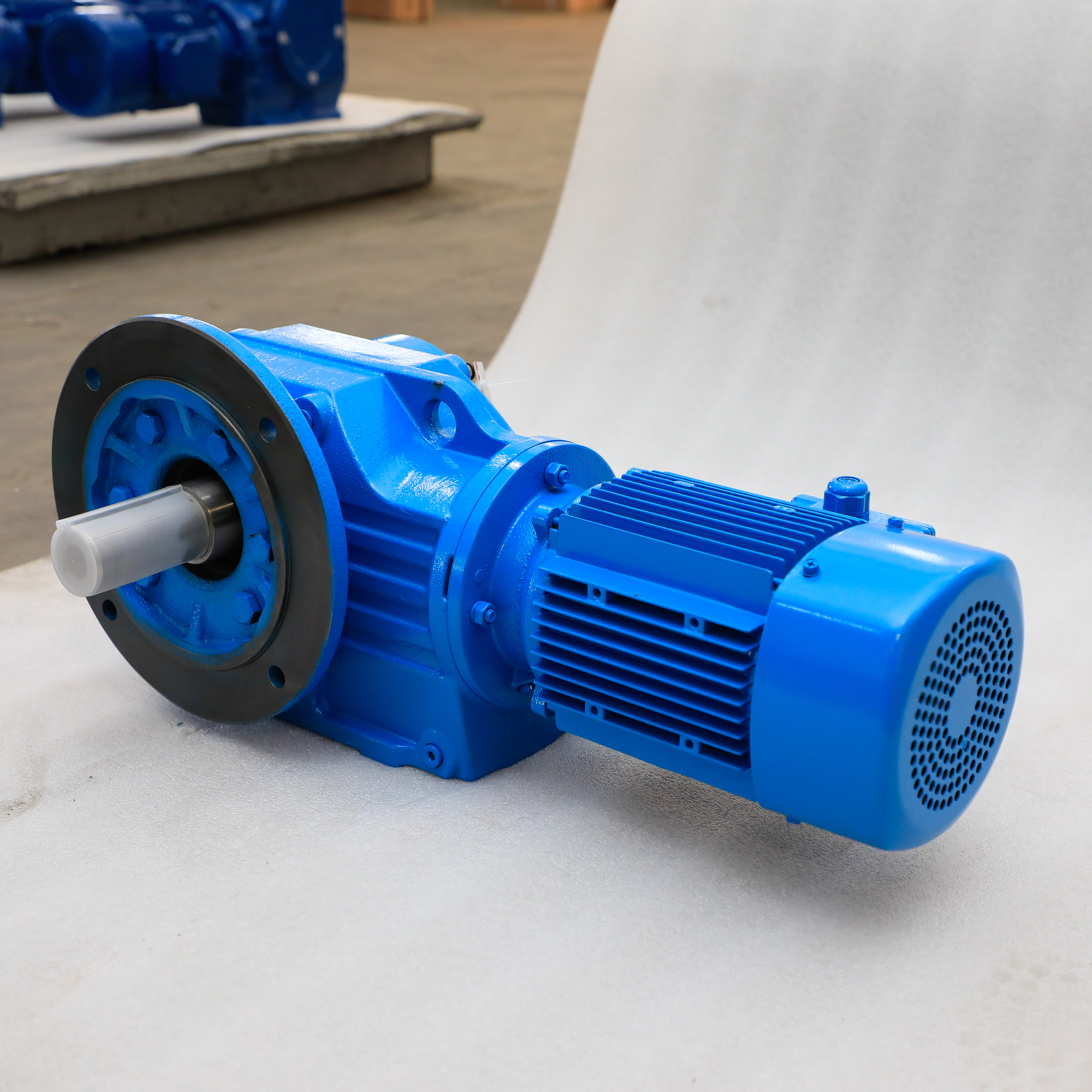
The flange-mounted mechanism relies on a standardized machined face. You bolt the unit directly to the face of the driven equipment. This utilizes a standard B5 or B14 flange pattern. This method completely eliminates the need for a separate baseplate. It is best for applications requiring a right angle helical gearbox to be integrated seamlessly into a machine casing. A sub-base becomes completely unnecessary. This approach simplifies the overall structural footprint. It keeps the machine profile exceptionally clean.
The shaft-mounted mechanism utilizes a hollow output bore. The gearbox housing slips directly onto the solid driven shaft of your machine. You must use a specialized bracket to prevent the housing from spinning. We call this bracket a torque arm. This configuration is best for dynamic loads and long conveyor systems. Space is typically at a premium in these environments. A compact bevel gear reducer absorbs sudden starting shock gracefully here. The setup accommodates slight shaft flex naturally. It does this without destroying the internal roller bearings.
You must constantly balance available floor space against expected load capacity. Sometimes you must abandon a traditional foot mount entirely. Tight factory layouts force a shaft-mounted approach to save critical floor space. However, you must evaluate the starting shock loads carefully. A simple torque arm cannot safely handle massive inertial spikes from giant crushers. Foot mounts manage extreme starting torque much better. Evaluate your peak loads before selecting a compact mounting style.
Alignment requirements differ significantly across mounting styles. Flange mounts offer incredibly fast installation. But they require strict manufacturing prerequisites. The machine builder must machine the mating face perfectly. Tight runout tolerances are strictly required here. Conversely, foot mounts are easier to physically swap out during an emergency failure. Yet, initial commissioning takes significantly longer. You must perform meticulous laser alignment. Shimming is mandatory during this delicate phase.
Environmental factors play a massive role in mounting selection. Washdown environments demand ultra-clean equipment designs. Flange and shaft mounts naturally eliminate underneath gaps. Debris, bacteria, and moisture typically accumulate beneath foot-mounted baseplates. Food-grade facilities strongly prefer gapless flange mounting. Heavy-dust environments also benefit immensely from this streamlined geometry. It prevents combustible dust from pooling under the drive unit.
Mounting Configuration Comparison Chart
| Mounting Type | Primary Advantage | Major Limitation | Ideal Application |
|---|---|---|---|
| Foot Mounted | Maximum structural rigidity; handles extreme shock. | Requires complex laser alignment and precision shimming. | Heavy extruders, large industrial mixers, crushers. |
| Flange Mounted | Eliminates baseplates; ensures concentric alignment easily. | Demands very tight machining tolerances on the machine face. | Pumps, integrated machine tools, cleanroom equipment. |
| Shaft Mounted | Saves floor space; accommodates slight shaft deflection. | Cannot support massive overhung radial loads safely. | Belt conveyors, bucket elevators, dynamic material handling. |
A soft foot occurs when mounting feet do not sit completely flush against the baseplate. You face a severe risk if you bolt a unit to an uneven surface. The rigid cast-iron housing will physically twist under bolt tension. This tiny structural twist instantly misaligns the internal gear mesh. Bearings bind up rapidly under this artificial load. You must use precision feeler gauges before tightening the foundation bolts. Add stainless steel shims to correct any gaps.
Torque arm installation errors ruin gearboxes constantly. Mechanics often make the common mistake of rigidly bolting both ends of a torque arm. This is a critical mechanical error. A torque arm must feature a pivot point or a rubber bushing. It must allow slight alignment flex during operation. If you restrain it rigidly, you induce massive radial loads. These unintended loads transfer directly into the driven shaft. The shaft will eventually snap under the fatigue.
Changing your mounting orientation alters internal fluid dynamics completely. Moving a flange mount from a horizontal position to a vertical position changes everything. The internal oil pooling shifts entirely. Operating the unit without adjusting the oil levels will cause an immediate disaster. The upper bearings will run completely dry. You must adjust the breather plug location. You must verify the new oil fill levels before starting the motor.
Use this logical framework to finalize your mounting strategy efficiently.
Step 1: Execute a Frame Audit. Examine the machine structure closely. Does the equipment have a heavily machined, rigid sub-structure? If you answer yes, select a Foot Mount. If the structure is weak or non-existent, a Shaft Mount works best.
Step 2: Conduct Load Profiling. Analyze the specific application forces. Does the application feature high overhung loads? Heavy chain sprockets and tensioned pulleys cause these destructive loads. If yes, verify the radial bearing load capacities for Foot or Flange mounts. Shaft mounts naturally eliminate overhung load issues entirely.
Step 3: Plan Future Serviceability. Map out your maintenance access routes. The maintenance team needs physical room to work. They must reach oil drains easily. Sight glasses must remain highly visible from walkways. Motor terminal boxes require clear access paths for electricians.
Take your finalized 3D CAD envelope and documented load duty cycle to the manufacturer. Consult directly with the gearbox application engineering team. They will run thermal and mechanical calculations. Let the experts lock in the final mounting type based on your precise data.
Selecting a mounting style is never a secondary afterthought; it remains a foundational design choice.
The mounting configuration directly dictates your mechanical footprint, structural integrity, and long-term maintenance schedule.
Foot mounts offer unparalleled rigidity for absorbing massive shock loads in heavy-industrial processes.
Prioritize shaft mounts for compact, direct-drive applications like material conveyors to save vital floor space.
Always finalize your spatial orientation before ordering to guarantee correct factory lubrication setup.
A: Typically no. While some modular gearboxes allow for bolt-on output flanges, the housing design and bearing configurations are often optimized for specific mounting styles. Retrofitting can alter stress distribution and void load ratings. Always order the correct factory-configured housing.
A: Without a torque arm, the rotational force of the motor would spin the entire gearbox housing rather than the driven shaft. The arm anchors the housing to the machine frame. It prevents rotation while allowing for slight, necessary alignment flex.
A: Gearboxes rely on splash lubrication. Changing the mounting orientation (e.g., M1 to M4) shifts where the oil pools internally. You must specify the exact mounting position when ordering so the manufacturer can correctly place the breather, drain, and level plugs.


