
- All
- Product Name
- Product Keyword
- Product Model
- Product Summary
- Product Description
- Multi Field Search


Views: 0 Author: Site Editor Publish Time: 2026-07-29 Origin: Site


An inline helical gear reducer is designed for straight-line power transmission. In many industrial drive systems, the motor, reducer and driven machine are arranged along the same centerline, making the inline layout compact, efficient and easy to integrate into standard machinery.
However, an inline layout does not mean shaft alignment can be ignored.
Even when the reducer structure is coaxial or inline by design, installation errors can still create misalignment between the motor shaft, reducer input shaft, reducer output shaft and driven equipment. Poor shaft alignment can increase bearing load, damage couplings, create uneven gear tooth contact, raise operating temperature and shorten reducer service life.
For straight-line industrial drive layouts, HUAKE’s Helical Gear Reducers can support stable torque transmission when shaft layout, coupling position and mounting conditions are properly confirmed.
This article explains how shaft alignment affects an inline helical gear reducer, what types of misalignment should be checked, and how proper installation can help improve reducer reliability.
Shaft alignment directly affects the performance and service life of an inline helical gear reducer. Although an inline reducer is designed for aligned power transmission, the motor, coupling, reducer and driven machine must still be installed correctly.
Key points include:
Inline layout reduces shaft direction complexity, but it does not eliminate alignment requirements.
Shaft misalignment can increase coupling stress, bearing load and gear tooth wear.
Poor alignment may cause vibration, abnormal noise, overheating and oil leakage.
Angular, parallel, axial, soft foot and thermal growth misalignment should all be considered.
Proper foundation, motor position, reducer mounting and coupling alignment are critical.
Alignment should be checked during installation and rechecked after trial running.
Long operating hours, high load and thermal expansion can change alignment over time.
Correct reducer selection and installation support can help reduce unnecessary downtime.
In short, good shaft alignment helps an inline helical gearbox deliver smoother torque transmission, lower vibration and longer operating life.
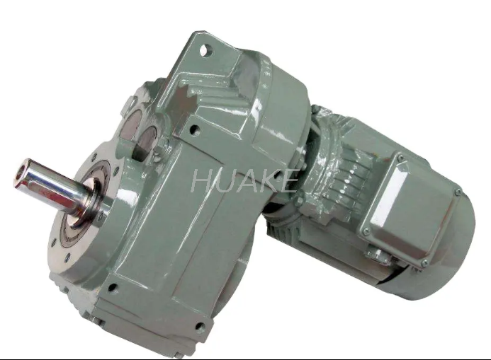
An inline helical reducer is built to transmit power along a straight path. The input and output shafts are usually arranged on the same axis or centerline. This makes the reducer suitable for compact and efficient industrial drive systems.
However, the reducer is only one part of the transmission system. The full system includes:
Motor
Coupling
Reducer input shaft
Reducer output shaft
Driven machine shaft
Mounting base
Fasteners
Foundation
Load connection
If any part of this system is not aligned correctly, extra force can be transferred into the reducer. Over time, this force may affect the gears, bearings, shafts, seals and housing.
Correct shaft alignment helps the reducer maintain:
Smooth gear meshing
Stable bearing load
Lower vibration
Lower operating noise
Better coupling life
More stable lubricant film
Reduced seal wear
Longer reducer service life
For industrial drive systems, shaft alignment is not only an installation detail. It is part of reducer reliability.
No. This is a common misunderstanding.
An inline helical gear reducer is designed for straight-line transmission, but actual alignment depends on installation. The motor shaft and reducer input shaft must be properly aligned. The reducer output shaft and driven machine shaft must also be properly aligned.
Misalignment can still occur because of:
Uneven foundation
Incorrect motor mounting
Poor coupling installation
Loose fasteners
Base frame deformation
Shaft runout
Incorrect flange connection
Thermal expansion during operation
Load movement after startup
Poor maintenance after long use
This means an inline layout can simplify the transmission path, but it cannot replace proper shaft alignment checks.
Shaft misalignment can appear in several forms. In real applications, more than one type may occur at the same time.
Angular misalignment occurs when two shafts meet at an angle instead of staying on the same straight line. This creates uneven coupling force and may increase bearing stress.
Parallel misalignment occurs when two shafts are parallel but not on the same centerline. Even if the shafts point in the same direction, the offset can create vibration and uneven load.
Axial misalignment occurs when the distance between shaft ends is incorrect. If the coupling is compressed or stretched beyond its suitable range, it may wear faster or transfer extra force to the reducer.
Soft foot occurs when one mounting foot does not sit evenly on the base. When bolts are tightened, the machine frame may twist slightly. This can distort alignment and create internal stress.
A system may be aligned when cold but become misaligned after heating. Motors, reducers, bases and driven machines may expand differently during operation. This is especially important in continuous-duty or high-temperature applications.
| Misalignment Type | What It Means | Main Risk |
|---|---|---|
| Angular misalignment | Shafts meet at an angle | Coupling stress and bearing load |
| Parallel misalignment | Shafts are parallel but offset | Vibration and uneven force |
| Axial misalignment | Shaft spacing is incorrect | Coupling compression or separation |
| Soft foot | Base does not sit evenly | Housing distortion and shifting |
| Thermal growth | Alignment changes after heating | Hot-running misalignment |
| Shaft runout | Shaft rotation is not concentric | Vibration and seal wear |
Shaft Misalignment
        ↓
Uneven Coupling Force
        ↓
Extra Bearing Load
        ↓
Uneven Gear Tooth Contact
        ↓
Vibration, Noise and Heat
        ↓
Lubrication Film Stress
        ↓
Accelerated Wear or Failure
This flow shows how a simple installation problem can gradually become a reducer reliability problem.
Helical gears are designed to engage smoothly. Correct contact between gear teeth helps distribute load evenly. If misalignment creates shaft deflection or uneven internal force, the gear tooth contact pattern may become uneven.
This can lead to localized stress, gear wear or pitting over time.
Bearings support the shafts and help maintain gear alignment. Shaft misalignment can create additional radial or axial force. This extra bearing load may increase heat, vibration and fatigue.
Since helical gears naturally generate axial thrust because of their angled teeth, correct bearing support and external alignment are both important.
Misalignment is a common cause of vibration and abnormal noise. When shafts do not rotate on the correct centerline, the coupling and reducer may experience cyclic force. This can create noise, vibration and unstable running.
In packaging machinery, food processing equipment, pumps and general industrial drives, vibration can also affect surrounding equipment.
The coupling connects the motor and reducer or the reducer and driven machine. If shaft alignment is poor, the coupling may compensate temporarily, but it will carry extra stress.
Over time, this can cause coupling wear, heat, cracking or premature failure.
Misalignment may cause shaft runout or uneven shaft loading. This can affect the shaft seal contact area. If the seal wears unevenly, oil leakage may occur near the input or output shaft.
Oil leakage is not only a cleanliness problem. Low oil level can also reduce lubrication and increase gear wear.
Misalignment can increase friction in bearings, couplings and gear contact areas. This may raise operating temperature. Higher temperature can reduce lubricant viscosity and weaken the oil film between gear teeth and bearings.
If overheating continues, reducer life may be shortened.
Misalignment affects several components at the same time. Gear teeth, bearings, couplings, shafts, seals and lubricant may all experience additional stress. This is why poor alignment can shorten reducer service life even when the reducer itself is correctly sized.
| Component | Effect of Misalignment |
|---|---|
| Gear teeth | Uneven contact, wear and pitting risk |
| Bearings | Extra radial or axial load |
| Shafts | Deflection and fatigue stress |
| Coupling | Heat, wear and premature failure |
| Seals | Uneven wear and oil leakage |
| Housing | Distortion if base is uneven |
| Lubricant | Higher temperature and oil film stress |
| Fasteners | Loosening caused by vibration |
| Driven machine | Unstable motion or process fluctuation |
Shaft misalignment may not be obvious immediately after installation. Some symptoms appear only after the reducer runs under load.
Common warning signs include:
Increasing vibration
Abnormal noise
Rising reducer temperature
Coupling wear
Oil leakage near shaft seals
Loose bolts
Uneven gear wear
Frequent bearing damage
Reduced operating stability
Shorter maintenance interval
If these symptoms appear, alignment should be checked before replacing parts. Replacing bearings or seals without correcting the alignment problem may only provide a temporary solution.
| Symptom | Possible Alignment Problem |
|---|---|
| Increasing vibration | Offset or angular misalignment |
| Abnormal noise | Uneven gear mesh or coupling stress |
| Rising temperature | Bearing load or lubrication stress |
| Oil leakage near shaft seal | Seal wear from shaft runout |
| Coupling wear | Poor motor-reducer alignment |
| Loose bolts | Base movement or vibration |
| Uneven gear wear | Internal or external alignment problem |
| Repeated bearing failure | Extra radial or axial load |
| Machine speed fluctuation | Coupling or driven shaft instability |
Proper installation is the best way to reduce misalignment problems. The following steps can help improve reducer reliability.
The base should be flat, rigid and strong enough to support the reducer, motor and driven equipment. An uneven foundation can cause soft foot, base stress and alignment drift.
Before tightening bolts, check whether the motor shaft and reducer input shaft are positioned on the correct centerline. The same should be done between the reducer output shaft and driven machine shaft.
Coupling alignment should be checked with suitable tools. Visual inspection alone is not enough for precision industrial drive systems.
Bolts should be tightened according to proper sequence and torque requirements. Uneven tightening may shift the motor or reducer position.
Mounting position affects oil level, lubrication path and shaft loading. Confirm whether the reducer is installed horizontally, vertically, foot-mounted or flange-mounted as required.
After trial running, the system may settle slightly. Heat, load and vibration can also affect alignment. Rechecking after initial operation helps identify early installation problems.
Alignment should be included in routine gear reducer maintenance, especially for high-load, continuous-duty or vibration-sensitive equipment.
HUAKE’s guide on gear reducer maintenance and shaft alignment explains why mechanical alignment and secure fastening are important for reducer reliability.
| Step | What to Check |
|---|---|
| Foundation | Flatness, rigidity and bolt position |
| Motor position | Centerline and shaft height |
| Reducer position | Mounting surface and shaft level |
| Coupling | Angular and parallel alignment |
| Shaft spacing | Correct axial distance between shaft ends |
| Fasteners | Tightening sequence and torque |
| Soft foot | Uneven base contact before tightening |
| Lubrication | Oil level and lubricant condition |
| Trial run | Noise, vibration and temperature |
| Recheck | Alignment after load and heat stabilization |
| Maintenance | Regular inspection during operation |
You should contact HUAKE when the reducer layout, load condition or alignment requirement is not clear. This is especially important when the drive system involves high torque, long operating hours, strict vibration requirements or limited installation space.
For coaxial transmission layouts, the R Series Helical Gear Hardened Gear Reducer can be considered when inline installation, stable output torque, low vibration and reliable speed reduction are required.
HUAKE can help users review:
Motor power
Input speed
Required output speed
Output torque
Gear ratio
Shaft layout
Coupling type
Mounting position
Operating hours
Load type
Working environment
Maintenance requirements
A correct inline reducer solution should match both the mechanical load and the physical installation layout.
Shaft alignment has a direct effect on the performance and service life of an inline helical gear reducer. Although inline reducers are designed for straight-line transmission, proper alignment is still required between the motor, reducer, coupling and driven machine.
Poor shaft alignment can cause uneven gear tooth contact, higher bearing load, coupling stress, vibration, abnormal noise, seal wear, oil leakage and overheating. Over time, these problems may lead to accelerated wear or unexpected downtime.
For reliable operation, users should check foundation flatness, shaft centerline, coupling alignment, mounting position, fastener tightening, lubrication condition and trial-run performance. Alignment should also be reviewed during routine maintenance, especially for high-load or continuous-duty applications.
Need help checking reducer layout or alignment requirements? Contact HUAKE for inline helical gear reducer selection support based on your motor power, input speed, output torque, gear ratio, shaft layout, coupling type, mounting position, duty cycle and operating environment.
Shaft alignment is important because poor alignment can increase bearing load, gear wear, coupling stress, vibration, noise and operating temperature. Correct alignment helps the reducer run smoothly and reliably.
No. An inline reducer is designed for straight-line transmission, but installation alignment must still be checked between the motor, reducer, coupling and driven machine.
Shaft misalignment occurs when connected shafts are not positioned correctly. It may be angular, parallel, axial or caused by soft foot, base distortion or thermal growth.
Misalignment can create uneven gear tooth contact. This may lead to localized stress, wear, pitting and shorter gear life.
Misalignment can add extra radial or axial load to bearings. This may increase heat, vibration and bearing fatigue.
Yes. Misalignment can create shaft runout or uneven seal wear, which may lead to oil leakage near the input or output shaft.
Common signs include vibration, abnormal noise, rising temperature, coupling wear, loose bolts, oil leakage and repeated bearing damage.
Check foundation flatness, confirm motor and reducer centerline, align the coupling properly, tighten fasteners correctly and recheck alignment after trial running.
Yes. Alignment should be rechecked after trial running because load, heat and base settling may change the original installation position.
Yes. HUAKE can help evaluate motor power, input speed, output torque, gear ratio, shaft layout, mounting position, coupling type and working environment to recommend a suitable inline helical gear reducer.


