
- All
- Product Name
- Product Keyword
- Product Model
- Product Summary
- Product Description
- Multi Field Search


Views: 0 Author: Site Editor Publish Time: 2026-10-17 Origin: Site


Do you know how heavy machines lift massive loads effortlessly while operating in highly confined spaces? Balancing high torque output within a tight physical footprint remains a major engineering challenge. Whether designing heavy-duty industrial machinery, advanced robotic arms, or intricate automotive transmissions, understanding how internal gears interact is crucial for maximizing mechanical efficiency.
Recent industry analyses reveal a massive shift toward hyper-compact automation. As automated guided vehicles and collaborative robots dominate modern warehousing, the engineering demand for drives delivering exceptional torque within a constrained radial footprint has skyrocketed. Equipment designers are moving away from bulky parallel shaft setups, opting instead for integrated solutions that maximize power density. We will break down the core components and explore the different structural configurations available today, helping engineers and procurement specialists select the optimal mechanical drive for their specific operational requirements.
Understanding the high-efficiency power transfer requires examining the physical architecture of these assemblies. The terminology used to describe this system is borrowed directly from our solar system. Internal components interact in a highly synchronized manner to distribute physical loads evenly across multiple contact points. This shared load distribution provides exceptional structural integrity and long-term durability.
Sitting in the exact center of the mechanism is the Sun Gear. Just like the actual sun, it rotates on a fixed central axis. In most standard industrial applications, this component acts as the primary input for power. It receives high-speed, low-torque rotational force directly from a connected motor shaft and immediately transfers that kinetic energy outward to the surrounding components.
Surrounding the central input are the smaller Planet Gear components. As the center gear turns, it forces these smaller gears to rotate on their own individual axes while simultaneously revolving around the center. To keep these orbiting gears perfectly aligned and spaced apart, they are mounted onto a robust bracket known as the carrier. Picture the carrier as a sturdy structural web holding the spinning gears in perfect harmony. In many speed reduction scenarios, this carrier serves as the power output shaft, delivering the newly multiplied torque directly to the driven machine.
The outermost component of the assembly is the annulus, commonly referred to as the Ring Gear. Unlike standard spur gears that feature teeth on their exterior, this component has internal teeth facing inward. It completely encloses the inner workings, meshing seamlessly with the outer edges of the orbiting planet gears. It serves two critical purposes: containing the internal lubrication while maintaining alignment, and acting as a stationary foundation. By holding this outer ring securely in place, the orbiting gears are forced to push against it, generating the massive torque output characteristic of these systems.
The fundamental engineering advantage of this system is its kinematic flexibility. Unlike parallel shaft gearboxes that offer a single fixed ratio based on their physical gear sizes, a planetary layout can produce multiple different outputs using the exact same set of internal parts. This is achieved through the mechanical concept of locking.
By holding one of the three main components completely stationary, applying input power to a second component, and taking the output from the third, the physical behavior changes entirely. Let us explore the practical scenarios commonly encountered on the factory floor.
Scenario: Maximum Reduction for High Torque
This is the most common configuration used in heavy industry. The outer ring is locked securely to the gearbox housing so it cannot move. The electric motor drives the central sun gear. Because the outer ring is stationary, the rotating center forces the planet gears to walk along the inside of the ring. Consequently, the carrier rotates in the same direction as the input, but at a significantly reduced speed. The physical trade-off for this speed reduction is a massive multiplication of rotational force.
Scenario: Overdrive for High Speed
In contrast, if an application requires an increase in speed rather than torque, the setup is reversed. The outer ring remains locked, but the input power is applied to the heavy carrier, and the output is taken from the central gear. Driving the heavy carrier requires substantial initial force, but it causes the smaller central gear to spin much faster than the input shaft. This overdrive ratio is frequently utilized in automotive transmissions for efficient highway cruising.
Scenario: Reversing Direction
To change the rotational direction of the output shaft without using external gears, the carrier is locked in place. The motor drives the center gear. Because the carrier cannot move, the planet gears can no longer orbit; they simply spin in place on their fixed pins. Acting as idler gears, they transfer the rotational force directly to the outer ring. This causes the ring to spin in the exact opposite direction of the input.
When specifying mechanical components for machinery, engineers must select the appropriate structural design to match the required load. While the basic physics remain identical, the internal configuration can be heavily altered. Understanding the specific Planetary Gearset types is crucial for optimizing machine performance and preventing premature mechanical failure.
Often referred to as a single-stage system, this is the most fundamental configuration. It consists of exactly one central gear, one single set of orbiting gears mounted on a single carrier, and one outer ring. Because power is transmitted through a single mesh cycle, these systems are highly efficient, often exceeding 97 percent mechanical efficiency. They are extremely compact in both diameter and length.
However, their primary physical limitation is the maximum gear ratio. A simple single-stage system typically maxes out at a reduction ratio of 10:1. Attempting to engineer a higher ratio in a single stage requires a central gear so small that it lacks the structural integrity to handle torque safely. They are best suited for standard factory automation, packaging machinery, and light-duty conveyors.
When engineers require higher reduction ratios or complex mathematical outputs but absolutely cannot afford to increase the physical length of the gearbox, they utilize compound configurations. This type introduces a more complex internal structure where the orbiting gears themselves are modified. For instance, in a meshed-planet setup, there are two sets of gears on the carrier that mesh with each other before connecting to the center or outer ring. Alternatively, a stepped-planet configuration features gears with two different tooth profiles machined onto the same solid shaft.
These complex internals alter the directional flow of power and allow for unique ratio combinations. They are particularly prevalent in aerospace actuators and heavy mobile machinery, providing complex gear ratios and reverse functionality within a highly constrained footprint.
Moving beyond basic applications, when industrial demands require extreme torque multiplication that far exceeds the 10:1 limit of a simple system, engineers turn to multi-stage designs. This architecture physically connects two or more simple gearsets together in a series within the same housing. The output carrier of the first stage is directly connected to the input gear of the second stage.
If a 10:1 stage is connected to another 10:1 stage, the total system ratio exponentially becomes 100:1. The trade-off for this massive torque is physical size and a slight drop in efficiency. Each added stage increases the overall length of the gearbox cylinder. Furthermore, because power must pass through multiple mesh points, mechanical efficiency drops slightly due to cumulative friction. These are the go-to solutions for heavy industrial mixing equipment, heavy-duty winches, and high-torque robotic joints.
Selecting the correct configuration is not merely a matter of preference; it is a strict engineering calculation based on space constraints, required torque, and target speed ratios. To streamline the decision-making process, engineers should evaluate the trade-offs carefully using standard industry benchmarks.
| Configuration Type | Typical Gear Ratio | Torque Capacity | Ideal Industrial Applications |
|---|---|---|---|
| Simple Single-Stage | 3:1 to 10:1 | Low to Medium | Packaging machinery, light conveyors, standard automation |
| Compound | 10:1 to 50:1 | Medium to High | Automotive transmissions, aerospace actuators, compact mobile machinery |
| Multi-Stage | 50:1 to 4000:1+ | Extreme | Heavy industrial mixers, mining winches, wind turbine yaw drives |
Specify a simple single-stage unit if your ratio requirements are below 10:1 and maximum energy efficiency is your top priority. In contrast, specify a compound unit if you need a non-standard mathematical gear ratio or internal reverse capabilities, but your machine design strictly forbids increasing the length of the gearbox housing.
Finally, specify a multi-stage unit when dealing with massive, heavy loads that require extreme torque multiplication. As long as your structural design can accommodate a longer axial footprint, multi-stage systems will deliver the raw pulling and lifting power required for heavy industry.
The widespread adoption of these systems across industrial sectors is driven by fundamental laws of physics. In a traditional parallel-shaft gearbox, power is transferred through a single point of contact between two gears. Conversely, a planetary system distributes the load simultaneously among multiple orbiting components. Because the physical stress is shared, the gears can be manufactured smaller while handling the exact same amount of power. This results in a significantly smaller footprint and lower overall weight.
Building upon this, the shared load distribution fundamentally changes how much force the system can withstand. The multiple gear meshes provide high torsional stiffness, making these systems highly resilient against sudden heavy shock loads. Additionally, because the gears are kept in constant, tight alignment by the outer ring, they can be manufactured with incredibly tight tolerances. This minimizes backlash, which is the slight gap between mating gear teeth. Low backlash is critical for exact positioning in CNC machining and servo-motor applications.
The theoretical advantages of these gear systems translate directly into measurable performance in the field. Different industries utilize specific configurations based on their unique operational demands.
In robotics and automation, precision multi-stage reducers are utilized in collaborative robotic arms. The low backlash ensures exact coordinate positioning, while the high torque allows the robot to lift heavy payloads smoothly without straining the servo motor. In the automotive industry, compound gearsets are the foundational technology behind automatic transmissions, allowing vehicles to shift seamlessly through multiple speeds within a compact chassis space.
Renewable energy also relies heavily on these mechanics. Imagine a wind turbine blade catching a sudden gust of wind; the massive blades rotate slowly but generate immense force. Heavy-duty multi-stage gearboxes are required to step up this slow, high-torque rotation into the high-speed rotation required by the electrical generator, safely absorbing unpredictable aerodynamic shock loads.
Specifying a mechanical drive requires precise mathematical calculation. Guessing or estimating load requirements will inevitably lead to catastrophic gear failure or motor burnout. Before contacting a manufacturer, engineering teams must define several critical parameters to ensure optimal performance and longevity.
First, determine your exact required gear ratio by calculating the difference between your motor input speed and the desired output speed of your driven equipment. Next, identify both the nominal continuous operating torque and the peak torque your machine will experience during startup or emergency stops. The gearbox must be rated to handle the absolute peak torque without shearing teeth.
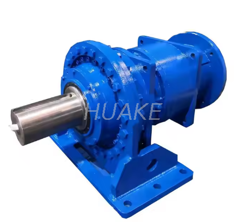
For demanding industrial applications, engineers frequently turn to robust solutions like the P-Series Planetary Gear Reducers. These heavy-duty units are engineered to deliver rated torque ranging from 22,000 Nm up to an astonishing 2,600,000 Nm. With ratio options spanning from 25 to 4000, they provide the exact mechanical advantage needed for mining, metallurgy, and heavy hoisting equipment.
Furthermore, consider the precision required. If your application involves simple continuous rotation, standard backlash is perfectly acceptable. However, if your application involves precise start-stop positioning, you must specify a low-backlash precision unit. Finally, assess the operating environment. Temperature extremes, dust exposure, and moisture dictate the external housing materials, internal lubrication, and sealing of the assembly.
All planetary systems rely on the elegant mechanical synchronization of the central sun gear, orbiting planet gears, and the stationary outer ring. However, choosing the correct internal configuration directly dictates your machinery performance limits. By carefully calculating your required speed ratios, torque loads, and spatial constraints, you can invest in the correct drive system, thereby preventing mechanical failure and optimizing overall efficiency for years to come.
If you are engineering a new heavy-duty machine or upgrading an existing production line, selecting the right gearbox is non-negotiable. Explore the high-performance P-Series and other customized mechanical drives at Huake Gearbox to find the exact torque and ratio configuration engineered for your toughest industrial challenges.
They are named after the mechanics of our solar system. The central gear acts as the sun, sitting stationary on its axis, while the smaller gears physically orbit around it exactly like planets revolving in space.
The sun gear rotates on a fixed central axis and usually acts as the power input driving the system. The planet gears are mounted on a movable carrier; they physically orbit around the sun gear while simultaneously spinning on their own individual axes.
Yes. While they are most commonly used as speed reducers to multiply torque, the system can act as an overdrive. If you input power through the carrier and take the output through the sun gear while locking the outer ring, the system will output a higher speed than the input.
Typically, a simple single-stage planetary system maxes out at a 10:1 reduction ratio. Attempting to engineer a higher ratio in a single stage requires a central gear that is too small to handle torque effectively, which is why multi-stage gearsets are utilized for higher ratio demands.
Premature failure is most commonly caused by inadequate lubrication, excessive thermal buildup, or subjecting the gearbox to shock loads that exceed its peak torque rating. Contamination from dust or moisture entering compromised seals can also rapidly degrade the internal gear teeth.
In the most common configuration where the ring gear is stationary and the carrier is the output, the ratio is calculated by dividing the number of teeth on the ring gear by the number of teeth on the sun gear, and then adding one to that result.


