- All
- Product Name
- Product Keyword
- Product Model
- Product Summary
- Product Description
- Multi Field Search


Views: 0 Author: Site Editor Publish Time: 2026-06-20 Origin: Site


Servo motors excel at precise positioning and dynamic speed control across modern industrial automation. However, running a bare servo directly coupled to a high-inertia load usually proves mechanically inefficient. You often face severe tuning difficulties when avoiding mechanical reduction, leading to unstable machinery.
Gearheads act as the essential bridge spanning the gap between a servo’s optimal high-speed operation and your application’s heavy torque demands. Without them, you must oversize the motor dramatically. This forces inflated hardware budgets and wastes considerable facility energy.
Among all gearing options, Planetary Gear Reducers remain the industry standard for servo applications. They deliver high torsional stiffness, maintain a compact footprint, and provide superior torque density. This article explores how these mechanisms solve inertia mismatches and preserve pinpoint accuracy. You will learn actionable steps to evaluate and specify the ideal reduction unit for your next motion control project.
Engineers consistently face a fundamental physical challenge when designing automation equipment. Servos provide unmatched electronic control, but they cannot bend the laws of mechanical physics. Direct-driving a massive load using a standard servo creates an immediate technical deficit.
The core issue revolves around inertia mismatch. The ratio between the load's inertia and the motor's rotor inertia dictates system stability. When this load-to-motor inertia ratio exceeds 10:1, the control loop struggles to keep up. In highly dynamic applications requiring fast indexing, even a 5:1 ratio causes severe problems. The motor strains to accelerate the mass, leading to mechanical resonance. You will often hear a distinct buzzing or whining noise from the drive train. Tuning the PID (Proportional-Integral-Derivative) controller becomes nearly impossible, resulting in overshooting and unstable positioning.
Furthermore, we must address speed and torque limitations. Servos naturally produce optimal power at high rotational speeds, often around 3,000 RPM. However, they generate relatively low continuous torque at these speeds. Direct-driving heavy loads at low speeds forces the motor to operate outside its optimal efficiency curve. To overcome this without gear reduction, you must select massive, expensive motors capable of delivering brute-force torque. This approach wastes capital and space.
A successful integration strategy must meet specific business criteria. First, it must reduce the required motor size. Smaller motors save upfront hardware costs and consume less electricity over their operational lifespan. Second, the solution must stabilize the control loop to ensure reliable, repeatable machine performance. Finally, the entire assembly must fit neatly within increasingly tight machine footprints.
Industry professionals rely on specific mechanical designs to overcome inertia and torque limitations. While spur, helical, and worm gears exist, the planetary architecture consistently outperforms them in motion control scenarios.
The primary advantage lies in its load distribution architecture. A central sun gear meshes simultaneously with multiple planet gears. These planets orbit the sun gear while engaging an outer ring gear. Because the design shares the mechanical load across multiple contact points, it yields the highest torque density per cubic inch. This means a surprisingly small gearbox can transmit immense rotational force without breaking.
High torsional stiffness represents another critical factor. When a machine accelerates or decelerates rapidly, inferior gearboxes experience "wind-up." The internal components twist elastically under stress. This elastic deformation ruins accuracy because the motor's encoder no longer perfectly matches the actual output shaft position. The robust design of Planetary Gear Reducers prevents this wind-up, ensuring absolute rigidity.
Motion control also demands low backlash capabilities. Backlash refers to the slight free play between mating gear teeth. Standard worm gears exhibit high backlash, which causes significant positioning errors during directional reversals. Conversely, you can configure a high-end Servo Planetary Gear Reducer to deliver minimal backlash, often down to 1-3 arcminutes. This enables zero-slip reversal for critical robotic and CNC tasks.
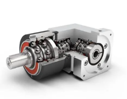
Finally, the coaxial form factor saves critical space. The inline design ensures the motor and gearbox share the same axis. This compact footprint proves invaluable inside cramped automation cabinets and complex robotic joints. Right-angle solutions work well when space dictates a 90-degree turn, but inline planetary units remain the default choice for pure efficiency.
| Gear Type | Torque Density | Backlash Potential | Form Factor | Best For |
|---|---|---|---|---|
| Planetary | Highest | Ultra-Low (<3 arcmin) | Inline (Coaxial) | High-dynamic servos, robotics |
| Spur | Low | Moderate | Parallel shaft | Simple low-torque conveyors |
| Worm | Moderate | High | Right Angle | Self-locking safety lifts |
Selecting the correct mechanical unit requires objective evaluation. Over-specifying drains project budgets, while under-specifying causes catastrophic machine failures. Follow this framework to shortlist the perfect specifications for your application.
You must understand how your machine moves before you review catalog specifications. Engineers commonly make the mistake of sizing a gearbox based entirely on continuous torque. This approach ignores the intense mechanical stress generated during acceleration and deceleration phases.
To avoid failure, evaluate these three distinct torque ratings:
| Torque Parameter | Symbol | Application Relevance | Sizing Rule of Thumb |
|---|---|---|---|
| Nominal Output | T2N | Steady-state running operations | Must exceed application continuous RMS torque. |
| Acceleration Peak | T2B | Fast indexing, starting, stopping | Motor peak torque × Ratio must not exceed T2B. |
| Emergency Limit | T2NOT | E-stops, power failures, crashes | Allows 1000 cycles maximum over lifespan. |
Backlash represents the lost motion between gear teeth. One arcminute equals 1/60th of a degree. While near-zero backlash sounds appealing, ultra-precision gears cost significantly more to manufacture.
You should align the backlash class with reality to control budgets. Choose ultra-precision gears (under 3 arcminutes) for laser cutting heads, multi-axis CNC machines, and surgical robotics. These applications fail if the tooling slips by even a fraction of a millimeter. For basic packaging conveyors or simple pick-and-place gantry systems, standard precision (8-12 arcminutes) works perfectly and saves considerable money.
Rotational torque only tells part of the story. You must evaluate the physical stress acting directly upon the output bearings. External forces push against the output shaft in two directions.
Radial loads push sideways against the shaft. You encounter heavy radial loads when mounting pulleys, belts, or pinions directly onto the gearbox. Axial loads push inward or pull outward along the shaft's centerline. If your design subjects the shaft to high radial or axial forces, verify the catalog bearing ratings. Upgrading to tapered roller bearings inside the output housing often solves premature failure issues in high-stress applications.
Gear ratio math solves the inertia mismatch problem. Because a gearbox reduces reflected inertia by the square of the ratio, a 10:1 gearhead reduces the load's reflected inertia by a factor of 100. This massive reduction allows a small servo to control a heavy load with absolute stability.
Most single-stage planetary units cover ratios from 3:1 to 10:1. If you need greater reduction, dual-stage units stack a second planetary gearset inside the housing, covering ratios up to 100:1. When choosing high ratios, carefully verify the maximum allowable input speed. Ensure your servo's maximum RPM does not exceed the gearbox's input thermal limit, otherwise friction will destroy the unit.
Even the most perfectly specified gearhead can fail during installation or field operation. Highlighting real-world pitfalls helps you avoid costly downtime.
Thermal derating in S1 (Continuous) duty causes frequent headaches. Planetary gear reducers trap heat inside their sealed housings. Fast-moving internal gears churn through the synthetic grease or oil, generating friction. Running high-ratio gearboxes at continuous high speeds prevents this heat from escaping. The internal temperature spikes, degrading the lubrication and melting the rubber shaft seals. If your machine runs continuously without pausing, you must carefully check the manufacturer's thermal capacity ratings. You might need to upsize the housing simply to gain more surface area for heat dissipation.
Direct mounting constraints also present severe risks. Many novice integrators fail to ensure perfect motor shaft alignment. Misalignment forces the motor shaft to rub aggressively against the gearbox input components. This generates severe vibration and fretting wear. To prevent this, always specify direct mounting flanges equipped with balanced clamping collars. These clamping systems securely grip the servo shaft, eliminating coupling vibration and ensuring perfect concentricity.
Acoustic noise and resonance can irritate operators and violate facility safety guidelines. Straight-tooth (spur) planetary gears sometimes whine loudly at high speeds because the gear teeth smash together simultaneously. If your environment requires ultra-smooth velocity or quiet operation, upgrade to helical planetary designs. Helical teeth engage gradually, acting as a verified upgrade path for noise-sensitive medical or laboratory automation.
Once you understand the engineering variables, you must transition from theoretical specifications to actual procurement. Navigating vendor catalogs requires a disciplined approach to ensure reliable system integration.
Begin by validating the vendor's engineering support tools. Leading manufacturers provide robust sizing software on their websites. This software allows you to input your specific motion profile and load parameters. The program then verifies inertia ratios and highlights potential thermal limit breaches automatically. You should also look for suppliers providing instant 3D CAD models. Downloading exact step-files ensures the gearbox fits seamlessly into your mechanical assembly drawings without late-stage redesigns.
Furthermore, demand clear documentation regarding bearing life. Reputable vendors openly publish L10h bearing life expectations based on input speeds and radial loads. This transparency ensures you know exactly when preventative maintenance should occur.
Before approaching vendors for quoting, compile your application data systematically. Prepare these specific data points:
Planetary gear reducers serve as much more than simple speed decreasers. They operate as critical inertia-matching devices that unlock the full dynamic potential of modern servo systems. By utilizing their high torque density and exceptional torsional rigidity, you guarantee precise motion profiles for demanding industrial machinery.
Success depends on avoiding common specification traps. Do not over-specify ultra-low backlash when standard precision suffices, as this heavily inflates project costs. Conversely, you must rigorously respect thermal ratings and peak acceleration limits to prevent premature bearing and seal failures during continuous operation.
Compile your exact motion profile, inertia ratios, and duty cycle requirements today. We strongly recommend consulting directly with application engineers to finalize the correct gearbox sizing and mounting configuration for your upcoming builds.
A: No. Standard gearboxes typically have excessive backlash, lower torsional rigidity, and lack the specific input flange configurations required for servo systems. High-dynamic servo shafts require secure clamping mechanisms to prevent slippage and fretting. Standard keyway connections found in AC gearboxes will quickly wear out under rapid servo reversals.
A: When properly sized and kept within safe thermal limits, these units deliver excellent longevity. Standard L10 bearing life expectations range from 20,000 to 30,000 operating hours. You must account for both nominal and peak acceleration torques during the sizing phase to achieve this lifespan without premature mechanical failure.
A: High input speeds generate significant friction at the input oil seal and the central sun gear. This friction leads to rapid thermal expansion and lubricant breakdown. Applications requiring continuous high RPMs demand specific thermal evaluations to prevent seal degradation and catastrophic internal component binding.


