
- All
- Product Name
- Product Keyword
- Product Model
- Product Summary
- Product Description
- Multi Field Search


Views: 0 Author: Site Editor Publish Time: 2026-08-16 Origin: Site


Selecting a premium gear unit represents just the first step in engineering reliable drive systems. Improper mounting remains the leading cause of premature bearing failure and catastrophic gear misalignment in the field. For engineers and maintenance managers, this physical integration phase dictates overall equipment reliability. It determines whether a drive system achieves its rated mechanical lifespan or introduces dangerous, unexpected production downtime. Even minor structural deflection translates directly into immense mechanical stress on internal components.
This guide covers the critical engineering tolerances you must strictly follow during installation. We explore standard mounting configurations, rigorous alignment thresholds, and strict evaluation criteria. You will learn how to properly mount a right angle bevel gear reducer without voiding warranties or compromising operational safety across your industrial facility. Following these steps ensures peak mechanical efficiency.
Alignment is paramount: Even micro-misalignments in base or shaft mounts will exponentially increase vibration and reduce gear life.
Orientation impacts lubrication: The mounting angle dictates oil levels, vent plug placement, and thermal dissipation limits.
Configuration matches application: Choosing between foot, flange, or shaft mounts depends entirely on footprint constraints, structural rigidity, and load transmission requirements.
Compact options exist for tight envelopes: Space limitations can often be solved by specifying a compact right angle gear reducer rather than engineering complex custom mounting brackets.
Mounting dynamics directly influence the mechanical longevity of any drive system. When engineers bolt a heavy housing onto an uneven foundation, they create structural deflection. The metal casing physically warps to match the uneven surface below it. This microscopic warping twists the internal shafts. Bearings then absorb uneven loads. They quickly overheat and fail prematurely. Poor foundation rigidity causes continuous vibration, which shakes seals loose and destroys gear teeth.
A successful installation achieves three specific outcomes. First, it ensures zero parasitic loads on the input and output shafts. Second, it maintains optimal gear mesh contact under full operational torque. Third, it allows predictable, easy maintenance access for your technicians. Mechanics must reach drain plugs, sight glasses, and breathers without dismantling adjacent machinery. Hitting these three targets guarantees smooth, reliable power transmission.
Compromising on installation tolerances introduces severe mechanical risks. High overhung loads bend shafts and destroy support bearings. Excessive vibration causes oil seal leakage, draining vital lubrication from the housing. Poor airflow around the mounting location triggers thermal overload. We frequently see these failures in crowded plant environments where installers rush the alignment process. You must adhere to standard engineering tolerances to protect your heavy machinery from rapid deterioration.
Industrial facilities utilize various mounting styles based on structural limits and application demands. You must evaluate the specific mechanical environment before selecting a configuration for an industrial right angle gearbox. Each style presents unique advantages and distinct engineering challenges.
Foot mounting remains the industry standard for heavy-duty applications. It provides maximum rigidity and excellent vibration dampening for high-torque systems. However, evaluating this setup requires strict attention to the foundation. You need a precisely machined, perfectly flat baseplate. Installers frequently use metal shims to correct minor base unevenness. While shimming works initially, it introduces long-term settling risks. Vibration can vibrate shims loose over time, causing the housing to shift out of alignment.
Flange mounts allow for direct motor coupling. This design eliminates heavy baseplates and drastically simplifies the alignment process. The motor bolts directly directly into the gearbox housing. This configuration is exceptionally easy to align during initial setup. However, it relies entirely on the structural integrity of the mating equipment. If the machine frame flexes under heavy loads, that flexing transfers directly into the gearbox housing. Flange mounts require highly rigid mating structures.
Shaft mounting works best for conveyors and applications where floor space remains at a premium. The gearbox slides directly onto the driven machine shaft. This approach completely eliminates traditional coupling alignment issues. However, you must utilize a torque arm to prevent the housing from spinning. Accurate torque arm positioning is absolutely vital. If you install the torque arm at the wrong angle, you will introduce severe bending stress into the housing and internal bearings.
| Configuration Style | Primary Advantage | Best Application Use | Key Evaluation Risk |
|---|---|---|---|
| Foot / Base Mount | Maximum structural rigidity | Heavy material handling | Foundation unevenness causes case twisting |
| Flange Mount | Simplifies direct motor alignment | Pumps, mixers, standard drives | Relies on mating frame stiffness |
| Shaft Mount | Eliminates external couplings | Conveyors, tight envelopes | Improper torque arm angle causes bearing failure |
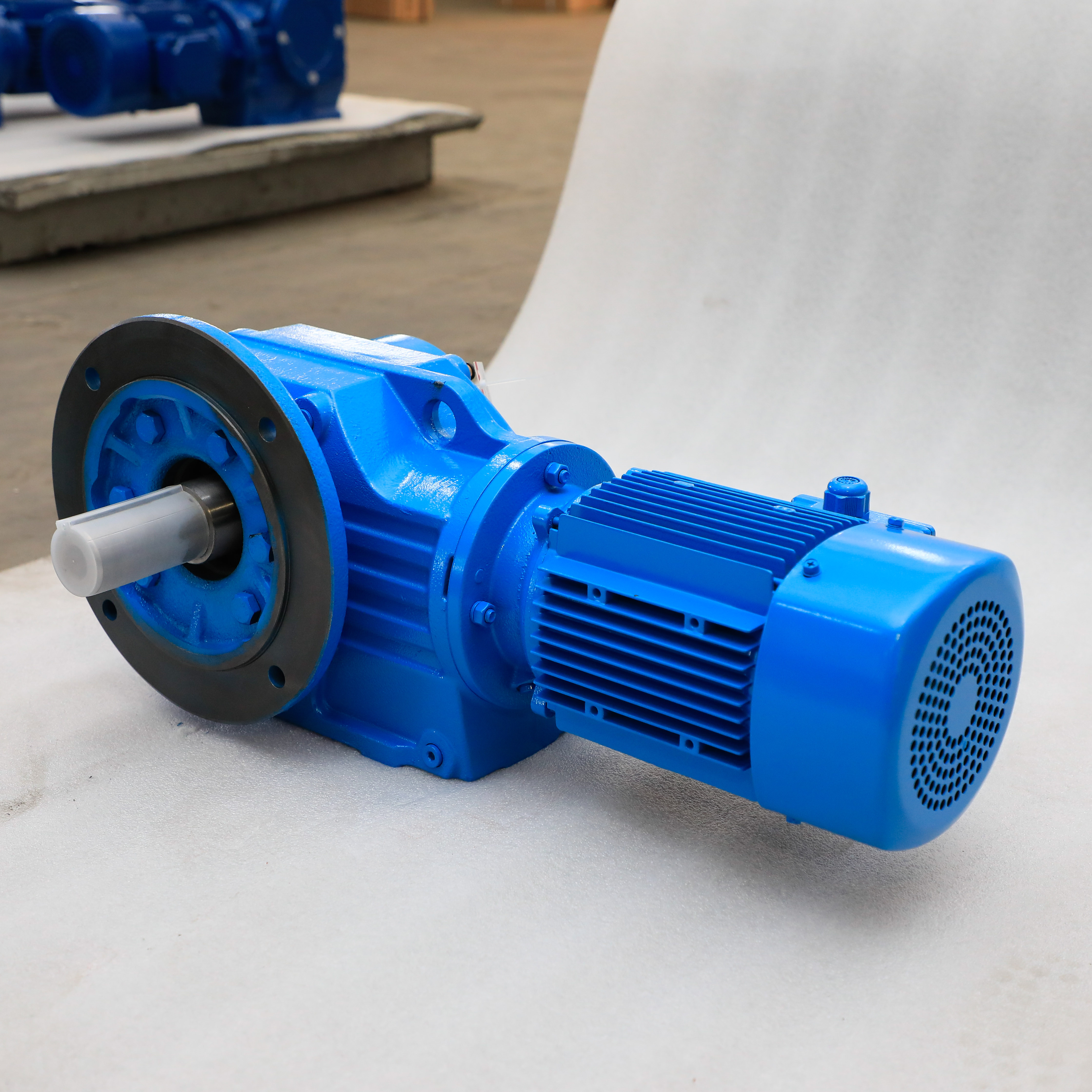
Proper preparation prevents catastrophic mechanical failures. Before hoisting any heavy unit into position, you must verify multiple physical constraints. Rushing this pre-installation phase guarantees alignment errors and premature wear.
Always assess the physical footprint before finalizing a design. Technicians need clearance to perform future oil changes and vibration analysis. When standard units crowd the maintenance envelope, do not modify the machine frame dangerously. Instead, pivot your design strategy. Specifying a compact right angle gear reducer often solves space limitations immediately. These specialized units deliver identical torque density while preserving vital access corridors for your maintenance personnel.
Base plate machining standards are non-negotiable. The mounting surface must be flat within a few thousandths of an inch. Bolting a rigid cast-iron housing down on an uneven surface twists the casing. This internal twist destroys gear mesh geometry instantly. Use precision levels and dial indicators to map the foundation. If you detect unevenness, you must machine the surface flat or use precision-ground steel shims correctly.
Coupling alignment requires extreme patience. You must measure and correct both parallel offset and angular misalignment.
Parallel Misalignment: Occurs when shafts run parallel but their centerlines do not match.
Angular Misalignment: Occurs when shafts meet at an angle, intersecting rather than running parallel.
Coupling Choice: Rigid couplings demand absolute perfection. Flexible couplings tolerate minor thermal growth, but you must never use them to excuse poor initial alignment.
The operating environment dictates your mounting hardware choices. Corrosive atmospheres require stainless steel fasteners and specialized epoxy coatings. Food-grade washdown environments demand specific drain orientations to prevent water pooling. Extreme ambient temperatures affect oil viscosity and thermal expansion. You must factor these environmental realities into your hardware selection before turning a single wrench.
Execution requires strict adherence to mechanical best practices. Follow this methodical sequence to ensure your drive system integrates perfectly with the surrounding machinery.
Preparation and Inspection: Thoroughly clean all mating surfaces using industrial solvents. Remove any rust-preventative coatings from the shafts. Check all keyways and keys for burrs or physical damage. Verify that the key fits snugly without excessive play.
Positioning and Fastening: Lower the unit carefully into position using appropriate rigging. Never use a hammer to force a coupling or shaft onto a gearbox. Impact shocks destroy internal bearings immediately. Instead, use proper heat-shrinking techniques or mechanical pullers to install interference-fit components. Tighten all foundation bolts using a calibrated torque wrench in a crisscross pattern.
Lubrication Positioning: Standard units ship sealed. You must adjust breathers, oil sight glasses, and drain plugs based on your final mounting orientation. If you mount the unit vertically, you must ensure the top gears are not starved of oil. Relocate the breather valve to the absolute highest point to prevent oil leakage during thermal expansion.
Initial Run-In Protocol: Never apply full production loads immediately. Execute a no-load test run for at least thirty minutes. Monitor the housing for irregular metallic noises. Check bearing locations for sudden temperature spikes using an infrared thermometer. Verify that the gear backlash matches manufacturer expectations. If vibration levels exceed normal limits, shut down and realign the system.
Even experienced installers make critical errors during complex integrations. Understanding these common pitfalls helps you proactively design better mounting strategies.
Metals expand significantly in high-temperature environments. If you rigidly bolt both the gearbox and the driven machine without allowing for shaft float, the shafts will grow as they heat up. This thermal growth pushes axially against the bearings. The resulting binding forces crush the bearings rapidly. You must utilize flexible couplings that accommodate axial thermal expansion, especially in hot ambient environments.
Overhung load represents the radial stress applied to a shaft by external components like belts, chains, or gears. Mounting sprockets or pulleys too far away from the gearbox housing exponentially amplifies this radial stress. It acts like a lever prying against the internal bearings. Always mount external drive components as close to the housing as physically possible. If your load exceeds catalog limits, you must install an outboard bearing block to support the shaft tip.
Shaft-mounted setups rely on torque arms to counteract rotational forces. Installing these arms at incorrect angles introduces severe binding forces into the system. As a strict rule, the torque arm should sit exactly at 90 degrees to a theoretical line connecting the driven shaft center to the arm's pivot point. Deviating from this 90-degree geometry pushes or pulls the housing off-center, causing rapid bearing failure and metal fatigue.
| Installation Pitfall | Mechanical Consequence | Preventative Action |
|---|---|---|
| Hammering couplings onto shafts | Brinelled bearings, cracked races | Use thermal expansion (heat) or mechanical pullers |
| Ignoring baseplate unevenness | Twisted housing, poor gear mesh | Machine baseplates flat or use precision steel shims |
| Incorrect breather placement | Pressurized housing, blown oil seals | Move breather to the highest port based on orientation |
Your mounting environment should dictate your purchasing decisions. You must match physical features to your desired operational outcomes. High-precision servo applications demand low backlash and extremely rigid mounting styles. Conversely, rugged material handling applications require heavy cast-iron bases capable of absorbing massive shock loads. Select a housing style that directly supports your specific load characteristics.
You must also decide between standard catalog options and custom-engineered solutions. Standard units cost less and ship faster. They suffice for the vast majority of industrial applications. However, when replacing obsolete equipment, standard footprints might not match your existing foundations. In these cases, purchasing a custom-machined interface often proves economically justified. It saves you from redesigning the entire machine frame or pouring new concrete foundations.
Collaboration prevents integration disasters. Work closely with an application engineer before finalizing your purchase. Provide them with accurate 3D CAD models of your equipment. Share your exact orientation requirements, ambient temperature data, and expected shock loads. They will cross-reference this data against catalog limits to provide a fail-proof recommendation. This proactive communication eliminates costly physical interference issues during installation.
Mounting a mechanical drive is a precision engineering task, not just a basic mechanical assembly step. Every bolt you tighten and every shim you place impacts the system's longevity. Precision alignment protects your internal components from devastating parasitic loads.
Foundation rigidity, proper configuration choices, and strict adherence to manufacturer tolerances directly dictate your operational success. Skipping steps during installation guarantees premature mechanical failure and costly production delays down the line.
We highly encourage readers to consult with internal engineering support teams before beginning any installation. Download technical sizing guides from the manufacturer to verify your specific mounting configuration. Proper planning today prevents catastrophic mechanical breakdowns tomorrow.
A: No. While many units are versatile, changing the final orientation usually requires critical modifications. You must relocate vent plugs to the highest point and adjust oil fill levels. Some orientations also demand modifying internal lubrication methods, such as adding internal splash guards or external forced lube systems to prevent dry running.
A: Specify a compact unit when your mounting envelope is severely restricted. Automated Guided Vehicles (AGVs) and tight conveyor frames often lack space. Using standard footprints here would require dangerous machine frame modifications or severely reduce access for maintenance technicians. Compact units solve these footprint issues safely.
A: Always mount sheaves, pulleys, and sprockets as close to the gearbox housing as physically possible. This reduces leverage against the internal bearings. If your calculated radial load exceeds the manufacturer's catalog ratings, you must consider adding external outboard bearings to properly support the extended shaft tip.
A: Flexible couplings are almost always recommended. They accommodate unavoidable thermal growth as machinery heats up. They also absorb microscopic micro-misalignments that occur during standard operation. This flexibility protects your internal gearbox bearings from dangerous parasitic loads and extends the life of your seals.


